TABLE A: CONTENTS AND ORGANIZATION
|
|
|
- Warren Richardson
- 5 years ago
- Views:
Transcription


1 Santa Ana Renaissance
2 T R A N S I T Z O N I N G C O D E : Table A: Contents and Organization TABLE OF CONTENTS AND CODE ORGANIZATION This Code is organized as identified below: TABLE A: CONTENTS AND ORGANIZATION Division 1. General Provisions Division 2. Regulating Plan and Zones Established Division 3. Urban Standards by Zones Division 4. Architectural Standards Sec. Title Pg Purpose and intent 1: Application of 1:3 Article Organization 1: Nonconforming 1:3 building and uses Affordable Housing 1:4 Develoment Incentives The Industrial overlay 1:4 Zone (I-OZ) Application for Discretionary Approval 1:5 Table 1A: Permitting Process Table 1B: Review Authority and 1:6 1:6 Permit Types Sec. Title Pg Zones Established 2:1 Figure 2.1: Regulating Plan 2: Uses Permitted 2: Operational Standards 2:3 Table 2A: Use Standards 2:3 Sec. Title Pg Building and Parking Placement, 3:1 Building Height and Profile, Encroachments, and Parking Summary Transit Village (TV) 3:3 Zone Downtown (DT) Zone 3: Urban Center (UC) 3:5 Zone Corridor (CDR) Zone 3: Urban Neighborhood 2 3:7 (UN 2) Zone Urban Neighborhood 1 (UN 1) Zone 3:8 Sec. Title Pg Building Types, General Provisions Table BT-1: Permitted Building Types General Requirements for All Types Figure BT-B: Permitted Height by Story Type Figure BT-C: Determining Permitted Building Size 4:1 4:1 4:3 4:3 4:4 Table BT-4: Open Space Area 4: Tower-on-Podium 4: Flex Block 4: Lined Block 4: Stacked Dwellings 4: Hybrid Court 4: Courtyard Housing 4: Live/Work 4: Rowhouse 4: Tuck-Under Housing 4: Bungalow Court 4: Duplex, Triplex, and Quadplex 4: House 4: Frontage Types 4:29 Table FT-1: Frontage Types Permitted by Zone 4: Arcade Frontage 4: Gallery Frontage 4: Shopfront Frontage 4: Forecourt 4: Stoop 4: Frontyard/Porch 4:33 1:1 T R A N S I T Z O N I N G C O D E
3 Table A: Contents and Organization, cont'd TABLE A: CONTENTS AND ORGANIZATION Division 4. Division 5. Network Concepts Division 7 Architectural Standards, cont'd On-Premise Signs Subdivision Guidelines Definitions Sec. Title Pg Sec. Title Pg Sec. Title Pg Sec. Title Pg Architectural Standards: Style, Massing, Proportions, and Materials Table AS-1 Permitted Architectural Styles by Building Type 4:35 4: Purpose and Intent Application of Division 5: General Provisions and definitions 5: Sign Standards 5:1 Table 1: Permitted Sign Types by Frontage 5: Sign Design 5: Sign Maintenance 5:3 Blocks and s 6:1 Purpose Guidelines Table 6A: Block Guidelines 6:1 Table 6B: Illustrative Sequence 6: Defintions 7:1 Architectural Style Guidelines Major Development Identification Signs Preservation of Existing Historic Signs 5:3 5:3 Network Concepts Sec. Title Pg Architectual Style Guidelines 4:35 Main 4:37 Commercial Building Identification Sign Building Directory Sign 5:3 5: Service Entry Wall Sign 5: Special Sale Sign 5: Credit Card Signs 5:4 Sec. Title Pg Purpose 6:3 Alignment and Adjustments New Types Mission Revival 4: Construction Signs 5:4 Art Deco 4:41 Folk Victorian 4:43 Craftsman 4:45 California 4:47 Contemporary Window Signs 5:4 Table 5C: Allowed Sign Types: Illustrated Table 2: Permitted Sign Placement 5:5 5:5 Figure 7-1: Network Plan Table 7A: Concepts for Specific s 6:3 6:5 Table 3: Requirements by Sign Type 5:7 T R A N S I T Z O N I N G C O D E 1:2
4 T R A N S I T Z O N I N G C O D E : General Provisions ARTICLE XIX. THE TRANSIT ZONING CODE, SPECIFIC DEVELOPMENT NO. 84 Division 1. General Provisions Sec Purpose and intent. (a) This article provides detailed regulations for development and land uses within the specific development area, and describes how these regulations will be used as part of the City s development review process. This article is intended to provide for the integration of new development and rehabilitation of existing structures with new and existing public transit infrastructure. This article will provide for: (1) A mixture of development and open spaces that situates commerce, work places, residences, and civic buildings within walking distance of transit and one another. (2) s that meet the needs of many transit modes including public transit, pedestrians, cyclists and automobiles. (3) Development that is maximally transit supportive. (4) New and remodeled buildings to work together to define the pedestrianoriented space of the public streets to support and strengthen the existing character of the neighborhoods in which they are located. (5) The repair and stabilization of the area's existing urban fabric, characterized by an interconnected gridded street pattern and a mixture of architectural styles and uses, in order to support the successful expansion of public tran sit and compatible development. Sec Application of Article (a) The Transit Zoning Code, as authorized by Chapter 41, Division 26, Section et seq., of the Santa Ana Municipal Code, is subject to the standards and regulations contained in this Article for the express purpose of establishing land use regulations and standards. All other applicable chapters, articles, and sections of the SAMC and any other regulations adopted by the City Council shall apply unless expressly stated or superseded by this Article. All terms contained herein shall be defined by the SAMC, unless specifically defined in this Article. (b) Proposed development, including the construction, reconstruction or structural alteration of a structure, subdivisions, and new land uses within the specific development area shall comply with all the applicable regulations established by this article. Sec Organization (a) Regulating Plan and Zones Established: Sections through 2008 defines the zones within the Specific Development (SD) boundaries, the parcels included within each zone, and describes, zone by zone, the standards for building placement, design, and use consistent with the permitted uses identified in Table 2A. (b) Use Standards: Table 2A identifies the land use types allowed by the City in each of the zones established by the Regulating Plan. A parcel within the Specific Development (SD) boundaries shall be occupied only by land uses identified as allowed within the applicable zone and the type of City approval required by Table 2A. (c) Urban Standards by Zone: Sections through 2015 regulates the features of buildings that affect the public realm. The urban standards regulate building and parking placement, height, and profile, and vary according to the parcel's zone applied by the Regulating Plan. Standards for items not explicitly described in this section, including but not limited to, walls and fences, mechanical equipment, trash bin enclosures, heliport and helipad, underground utility, installation of dish antennas, loading areas, parking lot design standards, refer to Chapter 41 of the Santa Ana Municipal Code and the Citywide Design Guidelines. (d) Architectural Standards: Sections through 2039 regulates the manner in which individual parcels and blocks are developed to create diverse and pedestrian-oriented development, through the use of three main components: (1) Sections through 2032 building types (e.g., duplex, rowhouse, courtyard housing) (2) Sections through 2039 frontage types (e.g., front yard/porch, stoop, arcade, shopfront) (3) Section (Table 4.3A) architectural styles (e.g., Main Commercial, Mission Revival, Art Deco, Folk Victorian, Craftsman, California Contemporary). (e) Sign Standards: Section regulates all signage within the SD boundaires to be consistent with the character described for each zone. (f ) Subdivision Guidelines: Establishes guidelines for the creation and maintenance of a finely grained and walkable network of blocks punctuated by integral and varied open spaces. (g) Network Concepts: identifies conceptual location and guidelines for the street network. This section rprovides guidelines the rights-of-way alignment, and width in plan and section with the corresponding details. (h) Definitions: Sections identifies and defines the terms used in this Code. 1:3 T R A N S I T Z O N I N G C O D E
5 1.0 - Applicability of Code, cont'd Sec Nonconforming buildings, structures and uses (a) A nonconforming building, structure or use shall comply with Article VI as modified as follows: (1) A building or structure that does not conform to the architectural style or story height requirements at the time of the adoption of this Article shall not cause the structure to be non-conforming. (2) Sections through shall not apply to this Article. (3) Rehabilitation, enlargement or exterior structural alterations of any nonconforming structure or structure occupied by a nonconforming use, except for structures occupied by single family and two-family dwellings, may be rehabilitated as follows: a. Rehabilitation limited to structural or non-structural alterations without any building expansion is permitted if: 1. All signage on the structure and the site on which it is located shall be brought into conformity with the signage requirements of this Chapter. 2. All outdoor storage shall be screened by a solid screen wall not to exceed 8 feet in height. Outdoor storage shall not exceed the height of the screen wall. 3. There shall be no increase in the number of dwelling units unless the site on which the structure is located complies with the off-street parking and open space requirements of this Chapter. 4. Architectural massing, features and detailing shall be modified to bring the structure into closer compliance with the architectural standards of this code, as deemed appropriate by the Executive Director of the Planning and Building Agency, or their designee. b. Rehabilitation may include expansion when the total floor area of all expansions occurring in any five-year period does not exceed ten (10) percent of the floor area as it existed at the beginning of the five years, provided that the following conditions are met: 1. All signage on the structure and the site on which it is located shall be brought into conformity with the requirements of this chapter. 2. There shall be no loading or unloading of vehicles between the hours of 10 pm and 7 am. 3. All outdoor storage shall be screened by a solid screen wall not to exceed 8 feet in height. Outdoor storage shall not exceed the height of the screen wall. 4. There shall be no enlargement which would intrude into any required yard. 5. There shall be no enlargement which would result in a new nonconformity with the requirements of this Chapter. 6. Off-street parking shall be provided in conformance with the requirements of this Chapter. 7. Landscaping shall be improved to bring the site on which the structure is located into closer compliance with the landscaping requirements of this Chapter, as deemed appropriate by the Executive Director of Planning and Building Agency, or their designee. 8. Architectural massing, features and detailing, shall be modified to bring the structure into closer compliance with the architectural standards of this Chapter, as deemed appropriate by the Executive Director of Planning and Building Agency, or their designee. (4) Rehabilitation, enlargement or exterior structural alterations of buildings occupied by a single family and two-family dwellings is permitted subject to the following: a. Structural alterations and additions may be made where the total floor area of all such expansions occurring in a five-year period does not exceed forty (40) percent of the floor space of the building as it existed at the beginning of said time, provided the number of dwelling units is not increased; and no new non-conformances with the requirements of this code are created. b. Structural alterations and additions which exceed forty (40) percent of the total floor area as it existed at the beginning of a five-year period; or remodeling which involves the demolition of more than fifty (50) percent of the building shall be permitted; provided that the following conditions are met: 1. Off-street parking shall be provided in conformance with the requirements of this Chapter. 2. No new nonconformities with the requirements of this Chapter are created. 3. A minimum of eight hundred (800) square feet of usable, continuous, non-front yard open-space, excluding driveways and parking areas is provided. Any open space with a minimum dimension of fifteen (15) feet by fifteen (15) feet shall be deemed continuous open space. c. Where rehabilitation of a building involves more than fifty (50) percent of a building wall which encroaches into a front or side yard setback and is demolished or is structurally altered, the remainder of the building wall shall be demolished. Any subsequent building wall shall conform to all provisions of this Chapter. d. An existing two-car garage with a minimum dimension of eighteen (18) feet by eighteen (18) feet exterior dimension shall be considered conforming. e. Remodel shall mean to reconstruct, or to make over in structure or style, but shall exclude re-roof, window replacement, exterior finish replacement and repair or similar modifications. Sec Affordable Housing Development Incentives. Any affordable housing project may use any or all of the following incentives pursuant to an Affordability Covenant Permit: (a) Parking Design Incentive: Allows for tandem parking not to exceed 30 percent of the required parking per residential unit. (b) Private Open Space Incentive: For purposes of meeting the private open space requirement, the private open space incentive allows for encroach ment into required front or side setbacks for porches that project from the main building facade up to 50 percent of the required setback, provided that the remaining setback area is not less than 5 feet. (c) Density Bonus Incentive: The state density bonus law, (California Government Code sections through 65918, as it may be amended from time to time) allows developers who guarantee that a portion of their residential development will be available to low income, very low-income or senior households to construct additional units beyond that permitted by the general plan land use element. This Specific Development does not place a limit on the number of units allowed provided that the project complies with the specified limitations on height, setbacks, floor area, open space, massing and other zoning regulations. a. For purposes of this section, the maximum density allowed shall be based on the highest number of the density range shown on table BT-1. b. All requests for density bonus shall follow the procedures and regulations established by Article XVI.I. T R A N S I T Z O N I N G C O D E 1:4
6 T R A N S I T Z O N I N G C O D E : Applicability of Code, cont'd Sec The Industrial Overlay (I-OZ) Zone (a) The Industrial Overlay Zone (I-OZ) is applied to areas zoned M1 or M2 and occupied with an industrial use at the time of the adoption of this Article. The zoning for the individual parcels shall be determined by Sectional District Map number as it appeared on May 1, (b) The I-OZ allows the M1 and M2 regulations to apply to said parcel until such time as the property owner applies to modify the zoning district. The Regulating Plan identifies the boundaries of the applicable zoning district (i.e. Transit Village, Urban Center, Corridor, Urban Neighborhood 1 or Urban Neighborhood 2) within the Transit Zoning Code. (c) A property owner may apply to develop the parcel consistent with the applicable zoning district within the Transit Zoning Code. The applicant shall receive all the necessary site approvals including, the approval of the overlay zone site plan pursuant to Article III, Division 28 prior to development. (d) The uses in the I-OZ shall be subject to the regulations of the M1 and M2 zones (SAMC 41, Article III, Divisions 18 and 19), as applicable. Sec Application for Discretionary Approvals (a) Site Plan Review shall mean specific development plan and shall comply with Sections through Sections through shall only apply to structures over four (4) stories in height. (b) Conditional use permits, variances and minor exceptions. Conditional use permits, variances and minor exceptions shall be subject to Article V, except for the permit thresholds for minor exceptions shall be as identified in Table 1B. 1:5 T R A N S I T Z O N I N G C O D E
7 Applicability of Code, cont'd TABLE 1A: PERMITTING PROCESS APPLICANT PLANNING DETERMINES APPLICABLE REVIEW PROCESS OVER-THE-COUNTER REVIEW DEVELOPMENT PLAN REVIEW B RIGHT B DISCRETIONAR ACTION P USES IN TABLE 2A APPLICATION IN COMPLIANCE WITH APPLICABLE STANDARDS MINOR EXCEPTIONS SELECTED CUP USES PARCEL MAPS CUP AND SPR USES VARIANCES TRACT MAPS EXTERIOR MODIFICATIONS ADDITIONS TO HISTORIC PROPERTIES MODIFICATIONS TO TRANSIT ZONING CODE ZONE CHANGES GENERAL PLAN AMENDMENTS APPROVAL AUTHORIT PLANNING APPROVAL AUTHORIT ZONING ADMINISTRATOR APPROVAL AUTHORIT PLANNING COMMISSION APPROVAL AUTHORIT HISTORIC RESOURCES COMMISSION PLANNING COMMISSION APPEAL TO PC APPEAL TO CC APPEAL TO CC APPROVAL AUTHORIT CIT COUNCIL PERMIT PROCESS PERMIT PROCESS PERMIT PROCESS PERMIT PROCESS PERMIT PROCESS TABLE 1B: REVIEW AUTHORIT AND PERMIT TPES [5] Key to Table CC PC HRC ZA Planning : City Council Planning Commission Historic Resources Commission Zoning Administrator Executive Director of PBA or their designee [1] Review Authority The Review Authority identified in Table 1B has the authority to grant approval of, or make a recommendation to the next higher Review Authority on the permit types as described. [2] Development Approval Applications that are consistent with the applicable standards of this code, and as further permitted by Table 2A, are to be approved administratively. [3] Modification of Standards i. Minor Exception. Upon determination by Planning that the request, as authorized by Table 1B, and is consistent with the required findings in the SAMC, the identified standards may be modified by the Zoning Administrator. ii. Variance. Requests that exceed the limits identified in Table 1B, but that are within the intent of this code, are to be processed by Planning with a recommendation for review and action by the Planning Commission, subject to the required findings in the SAMC. [4] Code Amendment Approval of a Code Amendment, subject to the required findings in the SAMC, shall be considered by the City Council upon recommendation by the Planning Commission. [5] Filing Fees. Applications submitted pursuant to this code shall be filed per the Planning Division s procedures and processing fees in effect at the time of application. Review Authority [1] Permit Type Permit Thresholds Planning Occupancy and Use Clearance for P uses in table 2A Development Approval [2] Sign Permit --- Voluntary Lot Merger --- Land Use Certificate Land use & building type Interpretations For 'LUC' uses in Table 2A ZA Parcel Map < 5 parcels Minor Exceptions [3] (all permit thresholds are the maximum minor exception permitted) --- (1) Lot Width / Depth 10% (2) Setbacks 15% (3) Building Height 10% (4) Building Size/Massing 15% (5) Driveway Access 15% (6) Open Space Area 15% (7) Sign Height/Width 10% (8) Walls and Fences 15% Conditional Use Permit for 'CUP' uses in Table 2A, as authorized by the Planning Commission Planning Commission Conditional Use Permit for CUP uses in Table 2A, except as noted above Site Plan Approval for 'SPR' uses in Table 2A Tentative Tract Map > 4 parcels Variance request is in excess of limits established for minor exception HRC Modific. to Historic Structures Placement on Historic Register City Council General Plan Amendments Zone Change change in zoning category Code Amendments [4] T R A N S I T Z O N I N G C O D E 1:6

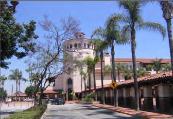
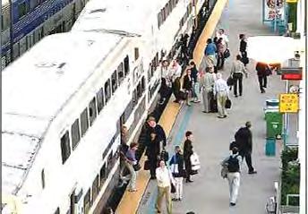
8 T R A N S I T Z O N I N G C O D E : Regulating Plan and Zones Established Division 2. Sec Zones Established (a) Purpose. This section establishes the zones applied to property within the plan area by the Regulating Plan. The Regulating Plan divides the plan area into separate zones that are based on a transect of intensity within the plan area that ranges from the most urban types of development and land use to the least urban types, with most zones providing for a significant mixture of land uses within them. Figure 2.1 Regulating Plan with Existing R.O.W ft This approach differs from conventional zoning maps that typically divide cities into zones that rigidly segregate residential, commercial, industrial, and institutional uses into separate areas, and thereby require residents to drive for nearly all daily activities. The use of zones based on development intensity (instead of land use zones) as the spatial basis for regulating development, directly reflects the functions of, and interrelationships between, each part of the plan area. The zones also effectively implement the City s urban design objectives for each part of the plan area, to establish and maintain attractive distinctions between each zone. This is why some parcels are zoned with more than one zone. In such cases, the zoning is divided along a clear boundary such as the middle of a block. The zones of this Regulating Plan allocate architectural types, frontage types, and land uses within the plan area, as well as providing detailed standards for building placement, height and profile. The diagram to the right identifies the 9 zones applied within the plan area as they relate to existing rights-of-way and parcels. (b) Zones established. The following zones are applicable to this specific plan, and applied to property within the boundary as shown on the Regulating Plan. (1) Transit Village (TV) Zone. The Transit Village zone is intended to provide standards for compact transitsupportive mixed-use/residential development. This zone is characterized by a wide range of building intensity, including mixed-use tower-on-podium buildings, flex blocks, liners, stacked flats, and courtyard housing. The zone accommodates retail, restaurant, entertainment, and other pedestrian-oriented uses at street level, with offices and flats above in the mixed-use building types, at high intensities and densities. The landscape palette is urban, with shading and accent street trees in parkway strips along Santa Ana Boulevard, and in sidewalk tree wells where on-street parking is provided. Parking is accommodated on-street, in structures with liner buildings, and underground. (2) Government Center (GC) Zone. This area accommodates a wide variety of civic uses, including Federal, State, and local government offices and services, libraries, museums, community centers, and other civic assembly facilities. Building types vary according to their public purpose, are programmed by the various government agencies for their specific sites, and therefore are not coded by the Transit Zoning code (SD-84A and SD 84B). The landscape style is urban, emphasizing shading street trees in sidewalk tree wells, and in landscaped public plazas. (3) Downtown (DT) Zone. This zone is applied to the historical shopping district of Santa Ana, a vital, pedestrian-oriented area that is defined by multi-story urban building types (flex blocks, live-work, stacked dwellings, and courtyard housing in the Downtown edges) accommodating a mixture of retail, office, light service, and residential uses. The standards of this zone are intended to reinforce the form and character represented by pre-world War II buildings and recognized as a National Historic District, through restoration, rehabilitation, and context-sensitive infill. The standards also facilitate the replacement or improvement of post-war development that eliminated the pedestrian orientation of various downtown blocks (for example, parking structures with no features of pedestrian interest along their entire lengths). The landscape style is urban, emphasizing shading and accent street trees in sidewalk tree wells. Parking is accommodated on-street and may also be in structures with liner buildings, underground, and within block centers in surface lots not visible from streets. (4) Urban Center (UC) Zone. This zone is applied to the area surrounding the Downtown, which serves as a transitional area to the surrounding lower intensity neighborhoods and to other areas where mixed-use and multi-unit residential buildings create a pedestrianoriented urban fabric. The zone provides for a variety of non-residential uses and a mix of housing types at medium intensities and densities. Besides accommodating community serving businesses, this zone may also serve the daily convenience shopping and service needs of nearby residents. Building types include mixed-use Flex Blocks, stacked flats, live-work, rowhouses, and courtyard housing. The landscape is urban, emphasizing shading street trees in sidewalk tree wells. Parking is accommodated on-street and may also be in structures with liner buildings and underground in areas adjacent to the DT zone, and in surface lots away from street frontages. (5) Corridor (CDR) Zone. This zone is applied to properties fronting existing commercial corridors and provides standards to improve pedestrian-orientation in a transit-supportive, mixed use area. Mixed-use flex block and live-work building types are at or near the sidewalk, and accommodate street level retail, service, and office uses, with office and residential above. The landscape style is urban, emphasizing shading street trees in sidewalk tree wells. Parking is accommodated on-street, and in screened surface lots between buildings, or away from streets, with no more than half the site frontage occupied by parking. (6) Urban Neighborhood 2 (UN-2) Zone. This zone is applied to primarily residential areas intended to accommodate a variety of housing types, with some opportunities for live-work, neighborhoodserving retail, and cafes. Appropriate building types include single dwellings, duplexes, triplexes and quadplexes, courtyard housing, rowhouses, and livework. In some areas, the more intense, hybrid court building type is allowed where additional intensity is warranted while maintaining compatibility with neighboring properties (see Regulating Plan). The landscape is appropriate to a neighborhood, with shading street trees in parkway strips, and shallow-depth landscaped front yards separating buildings from sidewalks. Parking is onstreet, and in garages located away from street frontages. (7) Urban Neighborhood 1 (UN-1) Zone. This zone is applied to existing primarily residential areas and is intended to strengthen and stabilize the low intensity nature of these neighborhoods. 2:1 T R A N S I T Z O N I N G C O D E

9 Regulating Plan and Zones Established, cont'd Appropriate building types include single dwellings, duplexes, triplexes, and quadplexes, and live-work. The landscape is appropriate to a neighborhood, with shading street trees in parkway strips and landscaped front yards separating buildings from sidewalks. Parking is on-street, and in garages located away from street frontages. (8) Industial Overlay (I-OZ) Zone. The I-OZ is applied to areas currently zoned M1 or M2, and occupied with an industrial use, to allow the types of land use activity and development permitted by existing M1 and M2 zoning to continue until such time that the owner chooses to apply the new zones identified in Figure 2.1. In order to determine if the M1 or M2 land use activity and development apply to a particular parcel, the I-OZ is further identified as I-OZ-M1 or I-OZ-M2. Until the property owner applies to modify the zoning district, property in the I-OZ shall be regulated by the provisions of the M1 and M2 zones (SAMC 41, Article III, Divisions 18 and 19), as applicable. (9) Open Space (O) Zone. This zone identifies areas reserved for community parks and other open spaces. Allowable structures in this zone are limited to those necessary to support the specific purposes of the particular open space area (e.g., sport-court enclosures and multi-purpose buildings in active parks, and trails within passive parks). Key Transit Village (TV) Government Center (GC) [1] Downtown (DT) Urban Center (UC) Corridor (CDR) Urban Neighborhood 2 (UN-2) H Location where Hybrid Court type is allowed Urban Neighborhood 1 (UN-1) Open Space (O)[1] Specific development Boundary Industrial Overlay Zone (I-OZ) I-OZ-M1 I-OZ-M2 [1] Identified, but not regulated by this Code, Refer to City requirements as identified in SAMC Chapter 41. T R A N S I T Z O N I N G C O D E 2:2
10 T R A N S I T Z O N I N G C O D E Uses Permitted Sec Uses Permitted. (a) Allowable Land Use Types. A parcel or building within the Specific Development area shall be occupied by only the land uses allowed by the table entitled Use Standards (hereinafter Use Standards Table) within the zone applied to the site by the Regulating Plan. (b) Garage sales are allowed in compliance with Section (c) Temporary outdoor activities are allowed in compliance with Section (d) outh amusement rides are permitted in compliance with Section for C1 districts. (e) Drive-through facilities shall not be permitted. Sec Operational Standards. (a) All property shall be maintained in a safe, sanitary and attractive condition including, but not limited to, structures, landscaping, parking areas, walkways, and trash enclosures. (b) All business activities shall be conducted and located within an enclosed building, except as allowed by Section of the SAMC and except that the following business activities may be conducted outside of an enclosed building: (1) Newsstands (2) Flower Stands (c) There shall be no manufacturing, processing, compounding, assembling or treatment of any material or product, other than that which is clearly incidental to a particular retail and service general enterprise, and where such goods are sold on the premises. (d) There shall be no work inside of a structure that generates noise that exceeds 60 db CNEL measured at the exterior wall of the unit. (e) Storage of goods and supplies shall be limited to those sold at retail on the premises or utilized in the course of business. (f) Public utility structures, including electric distribution and transmission substations shall be screened by a solid wall at least eight (8) feet high, except as restricted by Sections 36-45, 36-46, and (g) Any activity permitted shall be conducted in such a manner as not to have a detrimental effect on permitted adjacent uses by reason of refuse matter, noise, light, or vibration. (h) Small scale industry uses shall require a solid wall or fence not less than eight (8) feet in height along any rear or side lot line. Table 2A - Use Standards Permit Required by Zone Land Use Type TV DT UC CDR UN-2 UN-1 Refer to Key to Zone Symbols table on following page for zone description and use notations RESIDENTIAL Live-Work Use / Joint living-working quarters P (2) P (2) P (2) P (2) CUP CUP Care Homes CUP CUP CUP CUP CUP CUP Single Dwelling P P Multi-Family Dwellings P (1) P (1) P (1) P (1) P P RECREATION, EDUCATION AND ASSEMBL Community assembly P(1) P (1) P (1) P CUP CUP Health/fitness facility P P P P CUP --- Library, museum P P P P P CUP Schools P (1) P (1) P (1) P CUP CUP Studio P P P P CUP CUP Theater, cinema or performing arts P P P P Commercial Recreation (Indoor) CUP CUP CUP RETAIL General retail, except with any of the following features P P P P P(2) --- Floor area over 20,000 per tenant CUP CUP P --- CUP --- Eating establishments P P P P P(2) --- Auto or motor vehicle service P P SERVICE GENERAL Banquet facility/catering-sub. to (a) through (d) CUP CUP CUP CUP(1) Child day care - more than 8 and up to 14 children P (3) P (3) P P LUC(2) LUC Child day care center P (3) P (3) P P CUP CUP Adult day care center-subject to of the SAMC P (3) P (3) P P P --- Hotel, excl. transient residential hotel and long term stay P P P P Mortuaries, funeral homes CUP P Personal services P P P P P(2) P (2) Personal services - restricted CUP CUP CUP --- (i) All business activities, including, but not limited to, compounding, processing, packaging or assembly of articles of merchandise and treatment of products shall be conducted within a completely enclosed building. No ancillary vehicle maintenance or repair shall be allowed on site. (j) Loading areas shall not be visible from streets. Loading areas not facing a street shall be setback at least thirty-five (35) feet from the property line. 2:3 T R A N S I T Z O N I N G C O D E
11 Uses Permitted, cont'd Table 2A - Use Standards Land Use Type Permit Required by Zone TV DT UC CDR UN-2 UN-1 (k) No business activity that generates noise or vibration shall be conducted between 8:00 p.m. and 7:00 a.m. Monday through Friday and 8:00 p.m. and 10:00 a.m. Saturday and Sunday. (l) Operational standards for automobile servicing. SERVICES-BUSINESS-FINANCIAL-PROFESSIONAL Bank, financial services P P P P Business support service P P P P P(2) P (2) Clinic, urgent care CUP P Doctor, dentist, chiropractor, etc, office P(1) P(1) P(1) P Extended care P P P P CUP --- Professional / administrative/service office P(1) P(1) P(1) P P(2) P (2) (1) No automobile servicing shall be conducted before 7:00 a.m. or after 8:00 p.m. Monday through Friday and before 10:00 a.m. or after 8:00 p.m. Satruday and Sunday. (2) All work shall be conducted inside an enclosed structure. (3) Outdoor or overnight vehicle storage is not permitted. SMALL SCALE INDUSTR Artisan/craft product manufacturing CUP CUP CUP --- CUP --- Furniture and fixture manufacturing, cabinet shop P (3) --- P (3) Laboratory - medical - analytical --- P (1) P(1) P Manufacturing - light P (3) --- P (3) --- CUP --- Media production - office or storefront type (no sound stage) P P P(1) Printing and publishing --- P(1) P Research and development P (3) --- P (3) --- CUP --- TRANSPORTATION, COMMUNICATION, INFRASTRUCTURE Helistops CUP CUP Parking facility - public or commercial P P P P Transit station or terminal CUP CUP Public utility structure, excluding wireless comunication facilities CUP --- MISCELLANEOUS Any structure over four (4) stories in height SPR SPR SPR SPR SPR --- Businesses operating between 12 and 7 am CUP CUP CUP CUP CUP CUP Alcoholic beverage sales or consumption CUP CUP CUP CUP CUP --- Key to Zone Symbols TV Transit Village CDR Corridor DT Downtown UN-2 Urban Neighborhood 2 UC Urban Center UN-1 Urban Neighborhood 1 Key (1) Use permitted only on second or upper floors, or behind retail or service ground floor use. (2) Permitted only as part of a vertical mixed use project, with upper floor residential (3) Permitted only as part of a mixed use project with a commercial or residential component P use is permitted subject to compliance with all applicable provisions the Santa Ana Municipal Code LUC use is permitted subject to the approval of a Land Use Certificate. CUP use is permitted subject to the approval of a Conditional Use Permit. SPR use is permitted subject to the approval of Site Plan Review. --- use not permitted in particular zones. T R A N S I T Z O N I N G C O D E 2:4


12 T R A N S I T Z O N I N G C O D E : Urban Standards by Zones Division 3. Building and Parking Placement, Building Height and Profile, Encroachments, and Parking Summary A. Requirements 1. Purpose. This Division identifies the standards and requirements for new buildings, or buildings to be modified, for each zone within the Code area to ensure that proposed development is consistent with the City's goals for building form, character, and quality within the Code area. The zones are organized by intensity from the most intense (TV) to the least intense (UN-1). Unless stated otherwise, all requirements are expressed as 'minimums' and may be exceeded (e.g., 2 parking spaces required and 3 provided) in compliance with all applicable provisions of this code and Chapter Applicability. Each proposed improvement and building shall be designed in compliance with the standards of this Division for the applicable zone, except for public and institutional buildings, which because of their unique disposition and application are not required to comply with these requirements and are reviewed by a special permit and procedures. 3. Requirements by zone. Each proposed building shall be designed according to the urban standards identified per the zone in which the property is located. B. Summary of Zones At right, in Table 3A, are the six zones (see Note below) organized in descending order according to their role and intensity within the Code area and as they appear in this Chapter: Transit Village (TV) Downtown (DT) Urban Center (UC) Corridor (CDR) Urban Neighborhood 2 (UN-2) Urban Neighborhood 1 (UN-1) Note: the Government Center District and Open Space Zones are identified in this Code but regulated by the Santa Ana Municipal Code. Table 3A: ZONE SUMMAR OF STANDARDS 3.3 Transit Village (TV) Intent and Character of TV Zone Building Types Max Stories [a] (see Chapter 4.1 for standards) Tower-on-Podium 25 Flex Block 5 Lined Block 5 Stacked Dwellings 6 Hybrid Court - Courtyard Housing 5 Live-Work 3 Rowhouse - Tuck-Under 3 Bungalow Court - Duplex/ Triplex/ - Quadplex House - Frontage Types Allowed (see Chapter 4.2 for standards) Arcade Gallery Shopfront Forecourt Stoop - Frontyard & Porch - Building Setbacks in feet Front yard 0-10 [1] Side 0-10 [1] Side yard 0 Rear yard 15 Alley rear yard 3 [1] Grand Ave - Min 15', From current R.O.W 3.4 Downtown (DT) Intent and Character of DT Zone Building Types Max Stories [a] (see Chapter 4.1 for standards) Tower-on-Podium - Flex Block 10 Lined Block 5 Stacked Dwellings 6 Hybrid Court - Courtyard Housing 5 Live-Work 3 Rowhouse - Tuck-Under 3 Bungalow Court - Duplex/ Triplex/ - Quadplex House - Frontage Types Allowed (see Chapter 4.2 for standards) Arcade Gallery Shopfront Forecourt Stoop Frontyard & Porch - Building Setbacks in feet Front yard 0 Side 0-10 Side yard 0 Rear yard 15 Alley rear yard 3 Parking per DU or Sq Ft DU / Sq Ft + Guest Residential Live-Work 2 - Non-Residential 1/400 - In-Lieu Fee [b] yes yes Parking per DU or Sq Ft DU / Sq Ft + Guest Residential Live-Work 2 - Non-Residential 1/400 - In-Lieu Fee [b] yes yes Key to Table 3A Light shaded text means 'not permitted' in the zone. ' - ' means not applicable in the zone. [a] Max Stories for all zones refer to the total number of stories permitted per Zone. The massing for all buildings are subject to size and massing standards, as described in Building Type Standards for each building type (Section ), as indicated in the example table below. ALLOWED MASSING B STOR Ratio of Each Story in % of ground floor STOR % N/A [b] May be satisfied through In-Lieu Fee and Park-Once Program, if established 3:1 T R A N S I T Z O N I N G C O D E Notes continued on next page
 Intent and Character of UC Zone Intent and Character of CDR Zone Intent and Character of UN2 Zone Intent and Character of UN1 Zone Building Types Max Stories [a] (see")
 Tower-on-Podium - Flex Block 5 Lined Block 5 Stacked Dwellings 5 Hybrid Court - Courtyard Housing 5 Live-Work 3 Rowhouse - Tuck-Under 3 Bungalow Court - D u p l e x / Tr i p l e x /")
![- Quadplex House - Building Types Max Stories [a] (see 1 for standards) Tower-on-Podium - Flex Block 3 Lined Block - Stacked Dwellings - Hybrid Court - Courtyard Housing - Live-Work 3 Rowhouse -](/docs-images/87/95519815/images/13-2.jpg "Tuck-Under - Bungalow Court - D u p l e x / Tr i p l e x / - Quadplex House - Building Types Max Stories [a] (see 1 for standards) Tower-on-Podium - Flex Block - Lined Block - Stacked Dwellings -")
![Hybrid Court 5[1] Courtyard Housing 4 Live-Work 3 Rowhouse 3 Tuck-Under 3 Bungalow Court 2 Duplex/ Triplex/ 3 Quadplex House 2 [[1] see Regulating Plan for allowed location Building Types Max Stories](/docs-images/87/95519815/images/13-3.jpg "[a] (see 1 for standards) Tower-on-Podium - Flex Block - Lined Block - Stacked Dwellings - Hybrid Court - Courtyard Housing - Live-Work 2 Rowhouse - Tuck-Under - Bungalow Court 2 Duplex/Triplex 2")
13 Urban Standards by Zone, cont'd 3.5 Urban Center (UC) 3.6 Corridor (CDR) 3.7 Urban Neighborhood 2 (UN-2) 3.8 Urban Neighborhood 1 (UN-1) Intent and Character of UC Zone Intent and Character of CDR Zone Intent and Character of UN2 Zone Intent and Character of UN1 Zone Building Types Max Stories [a] (see Chapter 4.1 for standards) Tower-on-Podium - Flex Block 5 Lined Block 5 Stacked Dwellings 5 Hybrid Court - Courtyard Housing 5 Live-Work 3 Rowhouse - Tuck-Under 3 Bungalow Court - D u p l e x / Tr i p l e x / - Quadplex House - Building Types Max Stories [a] (see Chapter 4.1 for standards) Tower-on-Podium - Flex Block 3 Lined Block - Stacked Dwellings - Hybrid Court - Courtyard Housing - Live-Work 3 Rowhouse - Tuck-Under - Bungalow Court - D u p l e x / Tr i p l e x / - Quadplex House - Building Types Max Stories [a] (see Chapter 4.1 for standards) Tower-on-Podium - Flex Block - Lined Block - Stacked Dwellings - Hybrid Court 5[1] Courtyard Housing 4 Live-Work 3 Rowhouse 3 Tuck-Under 3 Bungalow Court 2 Duplex/ Triplex/ 3 Quadplex House 2 [[1] see Regulating Plan for allowed location Building Types Max Stories [a] (see Chapter 4.1 for standards) Tower-on-Podium - Flex Block - Lined Block - Stacked Dwellings - Hybrid Court - Courtyard Housing - Live-Work 2 Rowhouse - Tuck-Under - Bungalow Court 2 Duplex/Triplex 2 House 2 Frontage Types Allowed (see Chapter 4.2 for standards) Arcade - Gallery - Shopfront Forecourt Stoop Frontyard & Porch Frontage Types Allowed (see Chapter 4.2 for standards) Arcade - Gallery Shopfront Forecourt Stoop - Frontyard & Porch - Frontage Types Allowed (see Chapter 4.2 for standards) Arcade - Gallery - Shopfront Forecourt Stoop Frontyard & Porch Frontage Types Allowed (see Chapter 4.2 for standards) Arcade - Gallery - Shopfront - Forecourt - Stoop Frontyard & Porch Building Setbacks in feet Front yard 0 Side 0-10 Side yard 0 Rear yard 15 Alley rear yard 3 Building Setbacks in feet Front yard 5-15 [1] Side 0-10 [1] Side yard 0 Rear yard 15 Alley rear yard 3 [1] Grand Ave - Min 25' from current R.O.W. Building Setbacks in feet Front yard 10 [1] Side 10 Side yard 1 story 5 2 story 5 3 story 8 4 story 12 Rear yard 15 Alley rear yard 3 Building Setbacks in feet Front yard 20 Side 10 Side yard 5 [1] Rear yard 20 Alley rear yard 3 [1] Or varies [1] Grand Ave: Min 25' from current R.O.W. Parking per DU or Sq Ft DU / Sq Ft + Guest Residential Live-Work Non-Residential 1/300 - In-Lieu Fee [b] no no Parking per DU or Sq Ft Notes: The above table is a summary of the requirements by zone. Refer to the following chapters of this code for the full requirements per building type. The zones are arranged on a continuum of intensity with the most intense at left and the least intense at right. Each zone is aimed at generating or maintaining a distinct character through the allocation of appropriate building and frontage types and the placement of those types on parcels. DU / Sq Ft + Guest Residential Live-Work Non-Residential 1/200 - In-Lieu Fee [b] no no Parking per DU or Sq Ft DU / Sq Ft + Guest Residential Live-Work Non-Residential 1/300 - In-Lieu Fee [b] no no Parking per DU or Sq Ft DU / Sq Ft + Guest Residential Live-Work Non-Residential >750 sf: sf: 1 >1200 sf: - 1 per 300 s.f In-Lieu Fee [b] no no T R A N S I T Z O N I N G C O D E 3:2

14 T R A N S I T Z O N I N G C O D E Urban Standards - Zone Requirements Section Transit Village (TV) (a) Permitted buiding types and minimum and maximum height. Table TV-1, entitled Building Types and Mimimum and Maximum Height identifies the approved building types and the minimum and maximum height that is permitted for each building type within the TV zone subject to compliance with all applicable standards. Table TV-1. Building Types and Minimum and Maximum Height Building Types Min Stories Max Stories Tower-on-Podium 3 25 Flex Block 3 5 Lined Block 3 5 Stacked Dwellings 3 6 Hybrid Court not allowed not allowed Courtyard Housing 3 5 Live-Work 3 3 Rowhouse not allowed not allowed Tuck-Under Housing 3 3 Bungalow Court not allowed not allowed D u p l e x / Tr i p l e x / not allowed not allowed Quadplex House not allowed not allowed (d) Parking. (b) Building Setbacks. Front 1a see encroachments 1d Table TV-2 identifies the minimum setbacks required and, where noted, maximum setbacks permitted. The setbacks shall apply to all stories of a building. Table TV-2- Building Setback Standards. Setback Min. Max. (1a) Front yard 0' [a] [b] 10' (1b) Side 0' [a] [b] 10' (1c) Sideyard 0' Not applicable (1d) Rear yard 15' Not applicable (1e) Alley yard 3' Not applicable [a] In situations where the existing sidewalk is 10 feet or less in width, at the discretion of the City of Santa Ana, a setback greater than identified in the above table may be required to effectively result in a 10 foot wide sidewalk. [b] Setback at Grand Ave. is 15' minimum - 25' maximum measured from the right-of-way as it exists in 12/31/ b 1c see encroachments Side 1e 1e Alley where occurs (c) Frontage Requirements. a Per Table TV-1 Per Table TV-3 The ground floor fronting a street or other rightof-way (not including alleys) shall comply with the standards for the applicable frontage type, Sections thorugh and the Table TV-3 entitled Permitted Frontage Types. Table TV-3- Permitted Frontage Types Frontage Types % of frontage Permitted Arcade min. 50 Gallery min. 50 Shopfront min. 75 Forecourt Max. 50; remainder of frontage per permitted types (e) Encroachments. R.O.W. Frontage height and other requirements per Section Property Line Setback Line if parcel has side street frontage (1) Driveway Standards. Table TV-4 identifies the minimum and maximum width of driveways and permitted parking on driveways. Table TV-4 Driveway Standards Type Min Width Max Width 1-way 8' 12' 2-way 20' 25' Parking not permitted not permitted (2) Off-street parking standards a. Table TV-5 identifies the minimum off-street parking spaces that shall be provided. All fractions shall be rounded up to the next whole number. Front 2d 2a 2e 2c 2b Side Parking Permitted Alley where occurs Allowable Encroachment per table below a CURB 2c 2a,b R.O.W. 2c 2a,b Property Line Setback Line 2c 2b Min 2' clear of curb Table TV-5- Off- Parking Standards. Use-Type Parking Guest Parking Residential [b] 2 / unit min 0.15 / unit 3:3 T R A N S I T Z O N I N G C O D E In-Lieu [a] guest only Live-Work 2 / unit min - - Non-Residential 1 / 400 sq ft - yes [a] May be satisfied through In-Lieu Fee and Park- Once Program for TV District, if established [b] Permanent Special Need Housing including senior housing, will be parked at 1 space per unit minimum. b. Vehicular access to the off-street parking is permitted only from an alley or side street when present. Vehicular access to the off-street parking may be taken from primary street only when an alley or side street is not present. c. Parking setback standards. Table TV-6 identifies the minimum setback standards for the off-street parking. The setbacks shall apply to all stories of a building. Table TV-6- Parking Setback Standards. Setback Above Grade Subterranean (2a) Front yard Min. 40% design 0' min. lot depth (2b) side 10' min. 0' min. (2c) Side yard 0' min. 0' min. (2d) Rear yard 10' min. 3' min. (2e) Alley yard 3' min. 3' min. (1) Outdoor dining Such encroachments per approval of PBA (Planning & Building Agency) and PWA Directors, separate permit and agreement per SAMC. (2) Encroachments. Awnings, Signage, Balconies, Bay windows and Frontage Types may encroach into the required setback subject to the standards indentified in Table TV-7, entitled Encroachments. Table TV-7 Encroachments Encroachment Vertical Horizontal (2a) except awnings, and gallery min 8' max 18" and arcade frontage clear types (2b) (2c) except awnings, and gallery and arcade frontage types awnings, and gallery and arcade frontage types [1] Eave permitted to 3' of property line min 12' clear min 10'clear max 24" within 2' of curb Side yard N/A 0' Rear yard to eave [1] 5' Alley yard to eave [1] 3'
 (a) Permitted building types and minimum and maximum height Table DT-1, entitled Building Types and Mimimum and Maximum Height identifies the approved building types and the")
15 Urban Standards - Zone Requirements, cont'd Section Downtown Zone (DT) (a) Permitted building types and minimum and maximum height Table DT-1, entitled Building Types and Mimimum and Maximum Height identifies the approved building types and the minimum and maximum height that is permitted for each building type within the DT zone subject to compliance with all applicable standards, including Table DT-3 entitled Building Height. Table DT-1. Building Types and Minimum and Maximum Height. Building Types Min Stories Max Stories Flex Block 2 10 Lined Block 2 5 Stacked Dwellings 2 6 Hybrid Court not allowed not allowed Courtyard Housing 2 5 Live-Work 2 3 Rowhouse not allowed not allowed Tuck-Under Housing 2 3 Bungalow Court not allowed not allowed Duplex/Triplex/Quadplex not allowed not allowed House not allowed not allowed (d) Parking. ((1) Driveway Standards. Table DT-5 identifies the minimum and maximum width of driveways and permitted parking on driveways. Table DT-5 Driveway Standards Type Min. Width Max. Width 1-way 8' 12' 2-way 20' 25' Parking not permitted not permitted (2) Off-street parking standards a. Table DT-6 identifies the minimum off-street parking spaces that shall be provided. All fractions shall be rounded up to the next whole number. Table DT-6. Off- Parking Standards. Use-Type Parking Guest Pkg. In-Lieu [a] Residential [b] 2 / unit min 0.15 / unit guest only Live-Work 2 / unit min - - Non-Residential 1 / 400 sq ft - yes [a] May be satisfied through In-Lieu Fee and Park- Once Program for Downtown District, if estab lished. [b] Permanent Special Need Housing including senior housing, will be parked at 1 space per unit minimum. b. The parking requirements found in Table DT-6 shall apply only to new buildings, additional building area on existing buildings or conversion of existing building area to a new use. Conversion of building area of an historically designated building to a new use, where the building envelope is not increased in size shall have no parking requirement until such time as the City determines that 95 percent capacity on the five existing City controlled parking structures in the downtown has been reached. (b) Building Setbacks. Front Table DT-2 identifies the minimum setbacks required and, where noted, maximum setbacks permitted. The setbacks shall apply to all stories of a building. Table DT-2. Building Setback Standards Setback Min. Max. (1a) Front yard 0' [a] 0' (1b) Side 0' [a] 10' (1c) Side yard 0' No requirement (1d) Rear yard 15' No requirement (1e) Alley yard 3' No requirement Front 1a see encroachments 1d 1b [a] In situations where the existing sidewalk is 10 feet or less in width, at the discretion of the City of Santa Ana, a setback greater than identified in the above table may be required to effectively result in a 10 foot wide sidewalk. 2a c. Vehicular access to the off-street parking is permitted only from an alley or side street when present. Vehicular access to the off-street parking may be taken from primary street only when an alley or side street is not present. d. Parking Setback Standards - Table DT-7, entitled Parking Setback Standards identifies the minimum setback standards for the off-street parking. Table DT-7. Parking Setback Standards Setback Above Grade Subterranean (2a) Front yard min 40% lot 0' min depth (2b) side 10' min 0' min (2c) Side yard 0' min 0' min (2d) Rear yard 10' min 3' min (2e) Alley yard 3' min 3' min 1c see encroachments Parking Permitted Side 2c Side 1e 1e 2d 2e 2b Alley where occurs Alley where occurs (c) Building Height and Frontage Requirements. (1) Building Height Table DT-3 entitled Building Height identifies the maximum building height permitted based upon the lot width and as permitted by individual building Type (e) Encroachments (1) Outdoor dining - Such encroachments per approval of PBA and PWA Directors, separate permit and agreement. (2) Encroachments. Awnings, Signage, Balconies, Bay windows and Frontage Types may encroach into the required setback subject to the standards indentified in Table DT-8, entitled Encroachments. Table DT-8 Encroachments (2a) (2b) (2c) a (2)The ground floor fronting a street or other right-ofway (not including alleys) shall comply with the frontage requirements per Section and per the Table DT-4, entitled Frontage Requirements. Allowable Encroachment per table below a CURB 2c 1 2 2a,b R.O.W. Frontage height and other requirements per Section 4.2 R.O.W. Encroachment Vertical Horizontal except awnings, and gallery, min 8' max 18" and arcade frontage clear types except awnings, and gallery, and arcade frontage types awnings, and gallery, and arcade frontage types Building Height (stories) Lot Width Max. < 50 ft 3 stories 51 to 125ft 4 stories 125 to 175 ft 6 stories 175 ft 10 stories [1] [1] 100 ft setback from all R.O.W. required for stories Types % of frontage Permitted Arcade Min. 50 Gallery Min. 50 Shopfront Min. 75 Forecourt Max. 50; remainder of frontage per permitted types Stoop Max. 50 Min 2' clear of curb min 12' clear min 10'clear Property Line Setback Line T R A N S I T Z O N I N G C O D E max 24" within 2' of curb Side yard N/A 0' Rear yard to eave [1] 5' Alley yard to eave [1] 3' [1] Eave allowed to 3' of property line. 2c 2a,b Property Line Setback Line if parcel has side street frontage Table DT-3. Building Height Table DT-4. Frontage Types 2c 2b 3:4
 (a) Permitted building types and minimum and maximum height Table UC-1, entitled Building Types and Mimimum and Maximum Height identifies the approved building types and the minimum")
16 T R A N S I T Z O N I N G C O D E : Urban Standards - Zone Requirements Section Urban Center (UC) (a) Permitted building types and minimum and maximum height Table UC-1, entitled Building Types and Mimimum and Maximum Height identifies the approved building types and the minimum and maximum height that is permitted for each building type within the UC zone subject to compliance with all applicable standards. Table UC-1. Building Types and Minimum and Maximum Height. Building Types Min Stories Max Stories Tower-on-Podium not allowed not allowed Flex Block 2 5 Lined Block 2 5 Stacked Dwellings 2 5 Hybrid Court not allowed not allowed Courtyard Housing 2 5 Live-Work 2 3 Rowhouse not allowed not allowed Tuck-Under Housing 2 3 Bungalow Court not allowed not allowed D u p l e x / Tr i p l e x / not allowed not allowed Quadplex House not allowed not allowed (b) Building Setbacks. Front 1a see encroachments 1d 1b Table UC-2, entitled Building Setback Standards identifies the minimum setbacks required and, where noted, maximum setbacks permitted. The setbacks shall apply to all stories of a building. Table UC-2. Building Setback Standards. Setback Min. Max. (1a) Front yard 0' [a] 0' (1b) Side 0' [a] 10' (1c) Side yard 0' No reqmt (1d) Rear yard 15' No reqmt (1e) Alley yard 3' No reqmt 1c see encroachments Side [a] In situations where the existing sidewalk is 10 feet or less in width, at the discretion of the City of Santa Ana, a setback greater than identified in the above table may be required to effectively result in a 10 foot wide sidewalk. 1e 1e Alley where occurs (c) Frontage Requirements. a 1a 2a R.O.W. Frontage height and other requirements per Section 4.2 Property Line Setback Line if parcel has side street frontage The ground floor fronting a street or other right-of-way (not including alleys) shall comply with the standards for the applicable frontage type, Sections thorugh and the Table UC-3 entitled Permitted Frontage Types. Table UC-3. Permitted Frontage Types Frontage Types % of frontage Permitted Shopfront min 65 Forecourt max 50; remainder of frontage per allowed types Stoop max 50 Frontyard/Porch max 100 (d) Parking. (e) Encroachments (1) Driveway Standards. Table UC-4 identifies the minimum and maximum width of driveways and permitted parking on driveways. Table UC-4. Driveway Standards Type Min Width Max Width 1-way 8' 12' 2-way 20' 25' Parking not permitted not permitted Front 2c 2a 2d 2e Alley where occurs Allowable Encroachment per table below a 2c R.O.W. 2c Property Line Setback Line 2c (2) Off-street parking standards 2b 2a,b 2a,b 2b a. Table UC-5 identifies the minimum off-street parking spaces that shall be provided. All fractions shall be rounded up to the next whole number. Parking Permitted Side CURB Min 2' clear of curb Table UC-5. Off- Parking Standards. Use-Type Parking Guest Pkg Residential [a] 2 / unit min 0.15 / unit Live-Work 2 / unit min 0.15 / unit Non-Residential 1 / 300 sq ft - [a] Permanent Special Need Housing including senior housing, will be parked at 1 space per unit min. b. Vehicular access to the off-street parking is permitted only from an alley or side street when present. Vehicular access to the off-street parking may be taken from primary street only when an alley or side street is not present. 3:5 T R A N S I T Z O N I N G C O D E c. Parking setback standards. Table UC-6 identifies the minimum setback standards for the offstreet parking. Table UC-6. Parking Setback Standards. Setback Above Grade Subterranean (2a) Front yard min 50% lot depth 5' min (2b) side 5' min 5' min (2c) Side yard 5' min 5' min (2d) Rear yard 5' min 5' min (2e) Alley yard 3' min 3' min (1) Outdoor dining - Such encroachments per approval of PBA and PWA Directors, separate permit and agreement. (2) Encroachments. Awnings, Signage, Balconies, Bay windows and Frontage Types may encroach into the required setback subject to the standards indentified in Table UC-7, entitled Encroachments. Table UC-7. Encroachments Encroachment Vertical Horizontal (2a) except awnings min 8' clear max 18" (2b) except awnings min 12' clear max 24" (2c) awnings min 10'clear within 2' of curb Side yard N/A 0' Rear yard to eave [1] 5' Alley yard to eave [1] 3' [1] Eave allowed to 3' of property line.
 Permitted building types and maximum height Table CDR-1, entitled Building Types and Maximum Height identifies the approved building types and the maximum height that is permitted for each")


17 : Urban Standards - Zone Requirements Urban Standards - Zone Requirements, cont'd Section Corridor (CDR). (a) Permitted building types and maximum height Table CDR-1, entitled Building Types and Maximum Height identifies the approved building types and the maximum height that is permitted for each building type within the CDR zone subject to compliance with all applicable standards. Table CDR-1. Building Types and Maximum Height. Building Types Max Stories in CDR Tower-on-Podium not allowed Flex Block 3 Lined Block not allowed Stacked Dwellings not allowed Hybrid Court not allowed Courtyard Housing not allowed Live-Work 3 Rowhouse not allowed Tuck-Under Housing not allowed Bungalow Court not allowed Duplex/Triplex/Quadplex not allowed House not allowed (d) Parking. (b) Building Setbacks. Front 1a see encroachments 1d Side Table CDR-2, entitled Building Setback Standards identifies the minimum setbacks required and, where noted, maximum setbacks permitted. The setbacks shall apply to all stories of a building. Table CDR-2. Building Setback Standards. Alley where occurs Setback Min. Max. (1a) Front yard 5' [a] [b] 15' [b] (1b) side 5' [a] [c] 10' [c] (1c) Side yard 0' Not applicable (1d) Rear yard 15' Not applicable (1e) Alley yard 3' Not applicable [a] In situations where the existing sidewalk is 10 feet or less in width, at the discretion of the City of Santa Ana, a setback greater than identified in the above table may be required to effectively result in a 10 foot wide sidewalk. [b] Setback at Grand Ave. is 20' min - 30' max measured from R.O.W as it exists in [c] Setback at Grand Ave. is 15' min - 25' max measured from R.O.W as it exists in c 1c see encroachments 1b 1e 1e (c) Frontage Requirements. R.O.W. Frontage height and other requirements Table CDR -1 Table CDR-3 (e) Encroachments Property Line Setback Line if parcel has side street frontage The ground floor fronting a street or other right-of-way (not including alleys) shall comply with the standards for the applicable frontage type, Sections thorugh and the Table CDR-3 entitled Permitted Frontage Types. Table CDR-3- Permitted Frontage Types Frontage Types % of frontage Permitted Gallery min 65 Forecourt max 50; remainder of frontage per allowed types Shopfront min 65 (1) Driveway Standards. Table CDR-4 identifies the minimum and maximum width of driveways and permitted parking on driveways. Table CDR-4. Driveway Standards 2 a1 2d 2e R.O.W. Allowable Encroachment per table below Property Line Setback Line Type Min width Max width 1-way 8' 12' 2-way 20' 25' Parking not permitted not permitted Front 2a2 2c 2c Alley where occurs 2c 2a,b 2c 2c 2a,b 2b (2) Off-street parking standards Table CDR-5, entitled Off- Parking Standards identifies the minimum off-street parking spaces that shall be provided. All fractions in the parking calculations shall be rounded up to the next whole number. Table CDR-5. Off- Parking Standards. Use-Type Parking Guest Pkg Residential [a] 2 / unit min 0.25 / unit Live-Work 2 / unit min 0.25 / unit Non-Residential 1 / 200 sq ft - [a] Permanent Special Need Housing including senior housing, will be parked at 1 space per unit min. (3) Vehicular Access. Vehicular access to the offstreet parking is permitted only from an alley or side street when present. Vehicular access to the off-street may be taken from primary street only when an alley or side street is not present. Parking Permitted Side (4) Parking Setback Standards. Table CDR-6, entitled Parking Setback Standards identifies the minimum setback standards for the off-street parking. Table CDR-6. Parking Setback Standards Setback Above Grade (2 a1) Front yard 5' for 50% of lot width (2 a2) Front yard 20% of lot depth for 50% of lot width (2b) side 5' min (2c) Side yard 5' min (2d) Rear yard 5' min (2e) Alley yard 3' min Sidewalk (1) Outdoor dining. Such encroachments per approval of PBA and PWA Directors, separate permit and agreement. (2) Encroachments. Awnings, Signage, Balconies, Bay windows and Frontage Types may encroach into the required setback subject to the standards indentified in Table CDR-7, entitled Encroachments. Table CDR-7. Encroachments Encroachment Min Vertical Max Horizontal (2a) Front (2c) 8' clear 2' (2b) Side (2c) 10' 2' (2c) Awnings min 10' clear 2' Side yard Not applicable 0' Rear yard to eave [1] 5' Alley yard to eave [1] 3' [1] Eave permitted to 3' of property line. T R A N S I T Z O N I N G C O D E 3:6


![3 Tuck-Under Housing 3 Bungalow Court 2 Duplex/Triplex/Quadplex 3 House 2 [a] See Regulating Plan for allowable location (b) Building Setbacks.](/docs-images/87/95519815/images/18-2.jpg "Front see encroachments 1d 1a 1a 1c see encroachments 1d 1b Side Table UN2-2, entitled Building Setback Standards identifies the minimum setbacks required and, where noted, maximum setbacks permitted.")
18 T R A N S I T Z O N I N G C O D E Urban Standards - Zone Requirements Section Urban Neighborhood 2 (UN-2) (a) Permitted building types and maximum height. Table UN2-1, entitled Building Types and Maximum Height identifies the approved building types and the maximum height that is permitted for each building type within the UN-2 zone subject to compliance with all applicable standards. Table UN2-1. Building Types and Maximum Height. Building Types Max Stories in UN2 Tower-on-Podium not allowed Flex Block not allowed Lined Block not allowed Stacked Dwellings not allowed Hybrid Court 5 [a] Courtyard Housing 4 Live-Work 3 Rowhouse 3 Tuck-Under Housing 3 Bungalow Court 2 Duplex/Triplex/Quadplex 3 House 2 [a] See Regulating Plan for allowable location (b) Building Setbacks. Front see encroachments 1d 1a 1a 1c see encroachments 1d 1b Side Table UN2-2, entitled Building Setback Standards identifies the minimum setbacks required and, where noted, maximum setbacks permitted. The setbacks shall apply to all stories of a building. Table UN2-2. Building Setback Standards. Alley where occurs Setback Min. Other Min. (1a) Front yard 10' [a] 25' min (Grand Ave 2009 r.o.w.) (1b) side 10' [a] Not applicable (1c) Side yard 5'-1/2 story 8'- 3 story; 12'-4+stories (1d) Rear yard 15' Not applicable (1e) Alley yard 3' Not applicable 1c [a] In situations where the existing sidewalk is 10 feet or less in width, at the discretion of the City of Santa Ana, a setback greater than identified in the above table may be required to effectively result in a 10 foot wide sidewalk. 1e 1e (c) Frontage Requirements. R.O.W. Frontage height and other requirements Table UN2-3 Table UN2-1 Property Line Setback Line if parcel has side street frontage The ground floor fronting a street or other right-of-way (not including alleys) shall comply with the standards for the applicable frontage type, Sections thorugh and the Table UN2-3 entitled Permitted Frontage Types. Table UN2-3. Permitted Frontage Types Frontage Types % of frontage Permitted Shopfront min 65 Forecourt max 50; remainder of frontage per allowed types Stoop max 50 Frontyard/Porch max 100 (d) Parking. (e) Encroachments (1) Driveway Standards. Table UN2-4 identifies the minimum and maximum width of driveways and permitted parking on driveways. Table UN2-4. Driveway Standards Type Min Width Max Width 1-way 8' 12' or width of garage 2-way 20' 25' Parking [a] permitted permitted Front 2d 2e 2a 2c 2c 2b Alley where occurs R.O.W. Allowable Encroachment per table below a 2c Property Line 2a,b Setback Line 2c 2b [a] provided the vehicles on such driveway do not obstruct access to parking spaces serving any other unit (2) Off-street parking standards Parking Permitted Side Sidewalk Table UN2-5, entitled Off- Parking Standards identifies the minimum off-street parking spaces that shall be provided. All fractions in the parking calculations shall be rounded up to the next whole number. Table UN2-5. Off- Parking Standards. Use-Type Parking Guest Pkg Residential [a] 2 / unit min 0.25 / unit Live-Work 2 / unit min 0.15 / unit Non-Residential 1 / 300 sq ft - [a] Permanent Special Need Housing including senior housing, will be parked at 1 space per unit min. (3) Vehicular access to the off-street parking is permitted only from an alley or side street when present. Vehicular access to the off-street may be taken from primary street only when an alley or side street is not present. (4) Parking Setback Standards - Table UN2-6, entitled Parking Setback Standards identifies the minimum setback standards for the offstreet parking. Table UN2-6. Parking Setback Standards Setback Above Grade Subterranean (2a) Front yard 50% lot 10' min depth (2b) side 10' min 10' min (2c) Side yard 5' min 5' min (2d) Rear yard 5' min 5' min (2e) Alley yard 3' min 3' min 1. Outdoor dining - Such encroachments per approval of PBA and PWA Directors, separate permit and agreement. 2. Encroachments. Awnings, Signage, Balconies, Bay windows and Frontage Types may encroach into the required setback subject to the standards indentified in Table UN2-7, entitled Encroachments. Table UN2-7. Encroachments Encroachment Vertical Horizontal (2a) except awnings min 8' clear max 18" (2b) except awnings min 12' max 24" clear (2c) awnings min 2' 10'clear Side yard N/A 0' Rear yard to eave [1] 5' Alley rear yard to eave [1] 3' 3:7 T R A N S I T Z O N I N G C O D E [1] Eave allowed to 3' of property line.
 Zone 1 (UN-1) (a) Permitted building types and maxi mum height Table UN1-1, entitled Building Types and Maximum Height identifies the approved building types and")


19 T R A N S I T Z O N I N G C O D E Urban Standards - Zone Requirements, cont'd Section Urban Neighborhood Urban Neighborhood (UN1) Zone 1 (UN-1) (a) Permitted building types and maxi mum height Table UN1-1, entitled Building Types and Maximum Height identifies the approved building types and the maximum height that is permitted for each building type within the UN1 zone subject to compliance with all applicable standards. Table UN1-1. Building Types and Maximum Height. Building Types Max Stories in UN1 Tower-on-Podium not allowed Flex Block not allowed Lined Block not allowed Stacked Dwellings not allowed Hybrid Court not allowed Courtyard Housing not allowed Live-Work 2 Rowhouse not allowed Tuck-Under Housing not allowed Bungalow Court 2 Duplex/Triplex/Quadplex 2 House 2 (b) Building Setbacks. Front 1a see encroachments TableUN1-2, entitled Building Setback Standards identifies the minimum setbacks required. The setbacks shall apply to all stories of a building. Table UN1-2. Building Setback Standards. 1c 1d 1e see F2 (encroachments) 1b Side Setback Min. (1a) Front yard 20' (1b) side 10' (1c) Side yard 5' (1d) Rear yard 20' (1e) Alley yard 3' Alley where occurs (c) Frontage Requirements. R.O.W. 1a Property Line 2a Setback Line if parcel has side street frontage Frontage height and other requirements per Section 4.2 The ground floor fronting a street or other right-of-way (not including alleys) shall comply with the standards for the applicable frontage type, Sections thorugh and the Table UN1-3 entitled Permitted Frontage Types. Table UN1-3- Permitted Frontage Types Types Permitted % of frontage Stoop max 50 Frontyard/Porch max 100 (d) Parking. (e) Encroachments (1) Driveway Standards. Table UN1-4 identifies the minimum and maximum width of driveways and permitted parking on driveways. Table UN1-4. Driveway Standards Type Min Width Max Width 1-way 8' 12' or width of garage 2-way 20' 25' Parking [a] Permitted Permitted Front 2d 2e 2a 2c 2c 2b Alley where occurs R.O.W. 2a,b Property Line Allowable Encroachment 2a,b Setback Line 2a,c [a] provided the vehicles on such driveway do not obstrcut access to parking spaces serving any other unit (2) Off-street parking standards Table UN1-5, entitled Off- Parking standards identifies the minimum off-street park ing spaces that shall be provided. All fractions in the parking calculations shall be rounded up to the next whole number. TableUN1-5. Off- Parking Standards. Use-Type Parking Guest Pkg Residential [a] 2 / unit min 0.25 / unit Live-Work 2 / unit min 0.25 / unit Non-Residential: <750 sq ft 1 / unit min - Non-Residential: sq ft 2 / unit min - Non-Residential: sq ft / 500 s.f. - [a] Permanent Special Need Housing including senior housing, will be parked at 1 space per unit min. (3) Vehicular access to the off-street parking is permitted only from an alley or side street when present. Vehicular access to the off-street may be taken from primary street only when an alley or side street is not present. Parking Permitted (4) Parking Setback Standards - Table UN1-6, entitled Parking Setback Standards identifies the minimum setback standards for the off-street parking. Table UN1-6. Parking Setback Standards Setback (a) Front yard (b) side (c) Side yard (d) Rear yard (e) Alley yard Side Above Grade 20% lot depth 10' min 0' min 0' min 3' min 1. Outdoor dining - Not permitted. 2. Encroachments. Awnings, Signage, Balconies, Bay windows and Frontage Types may encroach into the required setback subject to the standards indentified in Table UN1-7, entitled Encroachments. Table UN1-7. Encroachments Encroachment Horizontal Vertical (2a) Porch max 5' see (2b) Bay window, balcony max 2' to eave [1] (2c) Side yard max 2' to eave [1] Rear yard 5' to eave [1] Alley rear yard 3' to eave [1] [1] Eave allowed to 3' of property line. T R A N S I T Z O N I N G C O D E A & 8 4 B 3:8
 Each proposed building shall be designed in compliance with the standards of the applicable building type.")

![Permtted Building Types Density Lot Depth Lot Width Stories Range [3] Building Types Allowed by Zone [2] min - max min - max max TV DT UC CDR UN-2 UN-1 A.](/docs-images/87/95519815/images/20-3.jpg "Tower-on-Podium ES ES 75-90 200' min 200'-250' 25 - - - - - B. Flex Block ES ES 30-40 130' min 75'-200'[4] 10 - - C. Lined Block ES ES 45-50 170' min 125'-300' 5 - - - D.")
![Stacked Dwellings ES ES 40-50 130' min 125'-200' 6 - - - E. Hybrid Court ES ES 45-50 160'-250' 150'-200' 5 - - - - [5] - F. Courtyard Housing ES ES 20-30 130'-250' 125'-200' 5 - - G.](/docs-images/87/95519815/images/20-4.jpg "Live/Work NO ES 12-15 100'-200' 75'-125' 3 H. Rowhouse ES ES 7-18 100'-200' 75'-150' 3 - - - - - I. Tuck-Under ES ES 12-18 75'min 94'-250' 3 - - J.")
![Bungalow Court ES ES 10-15 130' min 100'-180' 2 - - - - K. Duplex/Triplex/ ES ES 10-15 100' min 50'-125' 3 - - - - [6] Quadplex L.](/docs-images/87/95519815/images/20-5.jpg "House NO ES 5-7 100' min 40'-60' 2 - - - - = Permitted - = Not Permitted [1] The degree of mixed use depends on the particular zone in which the building is located.")
20 T R A N S I T Z O N I N G C O D E : Architectural Standards Division 4. Architectural Standards/Building Types. Sec Building Types, General Provisions. (a) Each proposed building shall be designed in compliance with the standards of the applicable building type. (b) Subject to the requirements of the applicable zone, a proposed building shall be designed as one of the building types permitted by the applicable zone by Table BT-1 entitled Permitted Building Types. A Tower-on-Podium B Flex Block G Live-Work H Rowhouse Building Type Multi- Family Mixed- Use [1] Table BT-1. Permtted Building Types Density Lot Depth Lot Width Stories Range [3] Building Types Allowed by Zone [2] min - max min - max max TV DT UC CDR UN-2 UN-1 A. Tower-on-Podium ES ES ' min 200'-250' B. Flex Block ES ES ' min 75'-200'[4] C. Lined Block ES ES ' min 125'-300' D. Stacked Dwellings ES ES ' min 125'-200' E. Hybrid Court ES ES '-250' 150'-200' [5] - F. Courtyard Housing ES ES '-250' 125'-200' G. Live/Work NO ES '-200' 75'-125' 3 H. Rowhouse ES ES '-200' 75'-150' I. Tuck-Under ES ES 'min 94'-250' J. Bungalow Court ES ES ' min 100'-180' K. Duplex/Triplex/ ES ES ' min 50'-125' [6] Quadplex L. House NO ES ' min 40'-60' = Permitted - = Not Permitted [1] The degree of mixed use depends on the particular zone in which the building is located. [2}In dwelling units per acre(du/ac). Each type is subject to the maximum stories allowed in each zone and the particular building size and massing requirements. [3] Measured along the front property line of the lot [4] This building type can be used on lots that have resulted from a legal subdivision provided there is a minimum frontage of 40 feet. [5] Allowed on specific locations only. [6] Quadplex not permitted in the UN-1 zone. L K J I H G M. HOUSE L. DUPLEX, TRIPLEX, & QUADPLEX K. BUNGALOW COURT J. TUCK-UNDER HOUSING I. ROWHOUSE H. LIVE \ WORK WALK-UP ACCESS 4:1 T R A N S I T Z O N I N G C O D E


 Point-Access")


21 4.0 - Architectural Standards, cont'd C Lined Block D Stacked Dwellings E Hybrid Court F Courtyard Housing I Bungalow Court J Tuck-Under Housing K Duplex/Triplex/Quadplex L House Below: This diagram identifies the range of building types used in the Code. The individual types are arranged on a continuum of intensity with the least intense at left and the most intense at right. Each type is allowed as identifiedon table BT-1 and its requirements are described on the following pages. Key for Illustrative Plan Diagram: Direct-Access (Walk-up access) Point-Access (Non-walk-up access) Point-Access (Tower) See Section 8.0 for definitions F E D C B A F. COURTARD HOUSING E. HBRID COURT D. STACKED DWELLING C. LINED BLOCK B. FLEX BLOCK A. TOWER-ON-PODIUM WALK-UP ACCESS NON-WALK-UP (POINT) ACCESS NON-WALK-UP (POINT) ACCESS PUBLIC PARKING GARAGE OR OTHER FACELESS STRUC- TURE T R A N S I T Z O N I N G C O D E 4:2

22 T R A N S I T Z O N I N G C O D E : Architectural Standards (c) All building types are subject to the following: (1) Lot width and Depth: a. The width and depth shall be determined as described below: All buildings shall be designed to an individual lot as required in Table BT-1. The lot is for design purposes and may be made permanent through the regular process for parcel or tract maps. Lot width and depth shall be determined as described below. 1- Front (Lot Width): Primary (Principal) Frontage 2- Side (Lot Depth) 3- Rear (Lot Width) PRIMAR STREET b. On corner lots fronting two streets, either street frontage may be used to comply with the lot width/frontage required per building type. c. Lots that have resulted from a legal subdivision but are less than 40 feet in width may be developed with standards that apply to lots 40 feet in width. (2) Access Standards: a. Where an alley is present, parking and services shall be accessed through the alley. b. Where an alley is not present, parking and services shall be accessed from the street through or alongside the building as permitted in the zone and this division. c. For corner lots without alley access, parking and services shall be accessed from the side street through or alongside the building. (3) Parking Standards: a. Entrances to garages, subterranean structured garages or driveways shall be located as close as possible to the side or rear of each lot. b. Surface parking lots shall not encroach into any required yards. ALLE (WHERE OCCURS) STREET (4) Service Standards: a. Services, including all utility access, above ground equipment, and trash enclosures shall be located on alleys b. Where alleys do not exist, services,including utility access, above ground equipment, and trash enclosures shall be located in compliance with the building location standards for the zone and this division. c. No trash enclosure shall be located in required landscape areas, within direct view of streets or in traffic or pedestrian aisles. d. Services and their appurtenances shall be screened from and shall not be located in required setback or landscaped areas. e. Each residential unit shall have access to on-site laundry facilities. f. Each development shall provide a trash area. g. Multiple family, commercial and industrial developments with common parking areas shall provide trash enclosures per h. Residential development providing individual trash containers shall provide an area that measures a minimum of 3.5 x 7, outside of required setbacks and yards, to store and place out for pick up. i. Individual trash bins located in a garage shall not encroach into the required parking area (5) Open Space Standards: a. Balconies are permitted in any setback yard as provided in the encroachment requirements of the applicable zone. b. Private patios may be provided at the side and rear yards. c. The area of any patio covers, gazebos and other roofed shade structures with at least 2 sides fully opened to the outside may be counted towards the required open space. d. Corridors, walkways, paseos, driveways, parking courts, lobbies and other such spaces shall not be included in the required open space calculations PRIMAR STREET (7) Frontage Standards: a. Frontage shall comply with the applicable standards set forth in Sections through (8) Building Size and Massing Standards: a. Buildings shall be constructed with a varied massing approach. Each building type contains an allowed massing by story table identifying the maximum ratio for each building story. Table BT-A identifies the information contain within each of these allowed massing by story tables. TABLE BT-A Allowed Massing by Story STOR Ground Floor Percentage of ground floor by story 100 Percentage number refers to the percentage of the ground floor footprint of the building area that is permitted for this particular story b. The maximum permitted ground floor footprint shall be determined as described in Figure BT-B c. Story heights 1. A story means a habitable level within a building from finished floor to finished ceiling. Specific requirements for a story in various configurations are identified in Table BT-2 Permitted Height by Story Type: Table BT-2: Permitted Height by Story type Type Location Minimum (ft) Maximum (ft) All building types, excluding house, duplex, Upper Floor(s) 9 14 triplex, and quadplex All building types, excluding house, duplex, Ground Floor triplex, and quadplex House, duplex, triplex, and quadplex Upper Floor 8 14 House, duplex, triplex, and quadplex Ground Floor 9 12 Garage Upper Floor(s) 8 14 Garage Ground Floor (podium) Equal to adjacent ground floor of building, or 8 feet if detached 2. A basements shall not be considered a story for the purposes of determining building height where the finished surface of the floor above the basement is less than six feet above grade plane 3. Attics shall not be considered a story for the purposes of determining building height. 4. Above ground garages occupying a level shall be considered a story for the purposes of determining building height. d. Dwelling Unit Types There are three basic dwelling unit types. 1. The flat is a single story unit. 2. The loft is a double-story heihgt unit that may have a mezzanine. 3. A townhouse is a two or more story unit. These dwelling units types may be used in any combination throughout a building, as permitted by the various buildings types. (9) Accessory Dwellings: a. Second dwelling units shall comply with the requirements established in Section of the Santa Ana Municipal Code. (10) Accessory Structures: a. The area occupied by accessory structures shall be included in the floor area ratio calculation. b. An accessory structure shall not encroach into any required open space or setback, except that a detached garage may be located 3 feet from the rear and interior side property line. 16 (6) Landscape Standards: a. All setbacks, yards and shared common open spaces shall be landscaped. b. A landscape buffer of not less than 5 feet shall be provided to separate any parking lot from an adjacent property. c. Surface parking lots shall be landscape per the City's Commercial area landscape standards. 4:3 T R A N S I T Z O N I N G C O D E


; 2b. Apply lot standards for each selected building type and identify lot(s) to receive a building.")
.")
.")

 shows two courtyard housing lots being designed for one courtyard housing building each. Figure BT-C.")
23 4.1 - Architectural Standards, cont'd Figure BT-B. Determining Permitted Building Size (Ground Floor Footprint) and Volume STREET PER FIG Alley per Fig 2.0 block / site per Fig 2.0 2a side: lot depth Alley rear rear 2a lot 2b front: lot width 2a interior side interior side lot 2b front: lot width 2a side: lot depth 3a 3b 3a Alley 3a 3b 3a 3a per Fig 2.0 Step 1: Existing Site Step 2: Apply Lots Step 3: Apply Building Setbacks 1a. If existing site meets subsection i or ii below, apply Table 6A, Subdivision Guidelines to generate a block(s): i. Site is not in compliance with Figure 2.1 or as adjusted by Network Concepts, section B,C. ii. Site exceeds the block dimensions per Table 6A, Subdivision Guidelines. 1b. If existing site already complies with the subdivision guidelines and street network concepts, proceed to step 2. Alley 2a. Per allowed building types identified in Table BT-1, select building type(s); 2b. Apply lot standards for each selected building type and identify lot(s) to receive a building. Illustrative Example: Plan Diagram Two adjacent courtyard housing buildings / lots Alley 3a. Per the standards in Division 3, apply the required setbacks to the lot(s). 3b. The result is the allowed building placement area on the lot(s). Illustrative Example: Axonometric Diagram Two adjacent courtyard housing buildings / lots 4a 4a 4b 4b Lot 1 Lot 2 Lot 1 Lot 2 Step 4. Apply open space requirements. See Figure BT-C 4a. Per the Open Space Standards of the applicable Building Type, subtract the required area to lot (e.g., 15%). Lot (to receive a building) (-) minus setbacks required (-) minus open space area required (=) equals 100% Ground Floor Footprint 4b. Apply Ground Floor Footprint to the allowed massing scenario to identify the maximum square footage permitted for the building. Step 5. Apply individual design 5a. Design the building(s), per the individual requirements of the selected building type(s) in Division 4. The example above (plan and axonometric diagrams) shows two courtyard housing lots being designed for one courtyard housing building each. Figure BT-C. Open Space Area Key In determining the ground-floor footprint, A required open space must be subtracted from the lot area whether or not the open space is at grade or on a podium Building Footprint Setbacks and Open Space A Garage Alley Illustrative Example: Site plan with either a raised podium or subterranean garage with the deck serving as part of required open space Illustrative Example: Subterranean garage with deck of garage serving as part of required open space A Illustrative Example: Podium garage with deck of garage serving as part of required open space A T R A N S I T Z O N I N G C O D E 4:4
 Tower-on-Podium is a multi-level building organized around a central core with the first two to five floors expressed as a podium building. (b) Lot Width and Depth.")
 Access Standards (1) Entrance to the tower shall be through a street level lobby. (2) Entrance to each ground floor unit shall be directly from the street at least every 50 feet.")
 Access to each unit above the third level, not accessed through a podium, shall be through a central interior corridor of at least 6 feet in width with recessed doors or seating alcoves/ offsets")
24 T R A N S I T Z O N I N G C O D E : Architectural Standards - Building Types Sec Tower-on Podium Building Type (a) Tower-on-Podium is a multi-level building organized around a central core with the first two to five floors expressed as a podium building. (b) Lot Width and Depth. The minimum lot width shall be 200 feet and the maximum lot width shall be 250 feet. The depth of the lot shall be a minimum of 200 feet. (c) Access Standards (1) Entrance to the tower shall be through a street level lobby. (2) Entrance to each ground floor unit shall be directly from the street at least every 50 feet. The entrance to each podium floor unit shall be directly from the podium. (3) Access to all other units shall be through a lobby and elevator. (4) Access to each unit above the third level, not accessed through a podium, shall be through a central interior corridor of at least 6 feet in width with recessed doors or seating alcoves/ offsets at least every 100 feet. (5) Each level of the building shall have access to the garage via an elevator. (6) Entrance to the residential portion of the building shall be through a dedicated street level lobby, or through a dedicated podium lobby accessible from the street or through a side yard. b Illustrative Axonometric Diagram (d) Parking Standards (1) Required parking shall be in a completely concealed garage. If the garage is partially or wholly on the ground, then it shall be lined by a commercial or residential units. (2) Dwellings shall have indirect access to their parking stall(s). (e) Service Standards (1) Utility meters shall be screened from view from the street and shall not be located within any required landscape or setback area. (2) Mail boxes shall not be located in any required open space, landscape or setback areas or detract from the primary entrance to the development. (f ) Open Space Standards (1) A quadrangle-shaped common open space (hereinafter 'quad') of at least 20 percent of the lot shall be located on the ground level, on a podium or on a roof garden. The quad shall be open to the sky. (2) Minimum dimensions for the quad shall be 60 feet in each direction. Permitted frontage types and architectural projections are permitted on all sides of the quad provided that the overall minimum dimension of quad is maintained. (3) Private open space shall be provided for each residential unit and shall be no less than 50 square feet with a minimum dimension of 6 feet in each direction. (4) Private open space may be substituted for additional common open space or common interior space, the size of which will be equivalent to the displaced private open space. The minimum dimension of this space shall be 20 feet in each direction. Illustrative Photo: Tower on Podium (g) Landscape Standards (1) A minimum of four (4), 36-inch box canopy trees shall be planted per quad. (2) Where side yards are present, one (1) 24-inch box tree per 30 lineal feet to protect privacy of neighbors. The trees may be placed in groups in order to achieve a particular design. (3) Smaller quads in interior courtyards will require shade tolerant plant materials. (4) Six (6), five-gallon size shrubs, ten (10) one-gallon size herbaceous perennials/shrubs and turf or acceptable dry climate ground cover shall be planted for every required tree. (h) Frontage Standards (1) Arcades, galleries, shopfront and forecourt may not encroach into the required minimum dimension of a quad. Illustrative Photo: Tower with stoop frontages (i) Building Size and Massing Standards (1) Buildings shall be composed of bases and towers. Bases shall be 2 to 5 stories with towers representing a proportionally smaller footprint as specified in Table BT-3, entitled Maximum Ratio for each Tower-on-Podium Story and composed as bundles of different heights to enrich the skyline of the City. (2) Buildings may contain any of 3 types of dwellings: flats, townhouses and lofts. (3) Units may be as repetitive or unique as deemed by individual designs. (4) Buildings may be composed of one dominant volume, flanked by secondary ones. (5) The Towers-on-Podium shall comply with the height ratios established in Table BT-3: Table BT-3. Maximum Ratio for Each Tower-on-Podium Story Maximum Ratio of each Tower-on-Podium Story STOR Ground Floor 2-5 % of ground floor by story 6-20 (or middle 3/5 of the building) (or top 1/5 of the building) 100% 100% 50% [1] 35% [1] For any percentage less than 100%, the percentage refers to the percentage of the ground floor footprint of the building area that is permitted for this particular story. (j) Accessory Dwellings. Accessory dwellings shall not be permitted. (k) Accessory Structures. Accessory structures shall not be permitted. Left: Illustrative Photo: Tower-on podium 4:5 T R A N S I T Z O N I N G C O D E

25 Architectural Standards - Building Types, cont'd KE TO CONFIGURATION EXAMPLES Point access podium (walk-up access permitted) PERMITTED USES The various floors of Tower-on-Podium are available for the uses identified in the diagram below subject to the requirements in table 2A, Land Use Standards. Tower (point-access) Ground Floor access required per frontage type standards KE O C/RT R USE OFFICE COMMERCIAL / RETAIL RESIDENTIAL O/C/R O/C/RT Surface Parking Subterranian Parking Illustrative Section Configuration Diagram Below: Examples of allowed Tower-on-Podium site configurations Central Asymetrical Distributed Max 70% of A Alley Alley Alley Min. 100' Min 200 Max 250 Primary street Min 200 Max 250 Primary street A Min 200 Max 250 Primary street A Alley Alley Alley Min. 100' Min 200 Max 250 Primary street Min 200 Max 250 Primary street Min 200 Max 250 Primary street T R A N S I T Z O N I N G C O D E 4:6

 Lot Width and Depth. The minimum lot width shall be 75 feet and the maximum shall be 200 feet. The depth of the lot shal be a minimum of 130 feet.")
 Access Standards (1) The main entrance to each ground floor unit shall be directly from the street.")
 Access to each unit above the second level, not accessed through a podium, shall be through an interior corridor of at least 6 feet in width with recessed doors or seating alcoves/offsets at at")
26 T R A N S I T Z O N I N G C O D E : Architectural Standards - Building Types b Illustrative Axonometric Diagram Illustrative Photo: Multi-Story example with shopfront frontage Illustrative Photo: Flex Block with shopfront frontage Illustrative Photo: Flex Block with arcade frontage Illustrative Photo: Flex Block with shopfront frontage Sec Flex Block Building Type (a) Flex Block is a building generally of a single massing element, designed for occupancy by retail, service, or office uses on the ground floor, with upper floors also configured for those uses or for residences. 1 (b) Lot Width and Depth. The minimum lot width shall be 75 feet and the maximum shall be 200 feet. The depth of the lot shal be a minimum of 130 feet. A flex block can be used in lots that have resulted from a legal subdivision with a frontage of at least 40 feet. (c) Access Standards (1) The main entrance to each ground floor unit shall be directly from the street. (2) Entrance to the residential portions shall be through a dedicated street-level lobby, or through a dedicated podium lobby accessible from the street or through a side yard. (3) Access to each unit above the second level, not accessed through a podium, shall be through an interior corridor of at least 6 feet in width with recessed doors or seating alcoves/offsets at at least 100 feet. (4) Each level of the building shall have access to the garage via an elevator. (d) Parking Standards (1) Required parking shall be accommodated in an underground garage, surface parking, tuck under parking, or a combination thereof. (2) Dwellings shall have indirect access to their parking stall(s). (e) Service Standards (1) Utility meters shall be screened from view from the street and shall not be located within any required landscape or setback area. (2) Mail boxes shall not be located in any required open space, landscape or setback areas or detract from the primary entrance to the development. (f ) Open Space Standards (1) The common open space shall be at the rear or side yard designed as a courtyard, or in the front as a forecourt. This area shall be equal to 15 percent of the lot and shall be open to the sky. Courtyards may be located on the ground or on a podium. Side yards may also be formed to provide outdoor patios connected to ground floor commercial uses to serve as additional open space. (2) Minimum courtyard dimensions shall be 40 feet when the long axis of the courtyard is oriented EW and 30 feet for a NS orientation. Courtyard proportions shall not be less than 1:1 between the width of the courtyard and the height of the building for at least 2/3 of the court's perimeter. Horizontal shifts in upper floors adjacent to a court may not exceed 1/2 the height of each upper floor. (3) In 40 foot wide courtyards, frontages and architectural projections are permitted on two opposing sides of the courtyard provided that an overall minimum width of 40 feet is maintained. Frontages and architectural projections are permitted on one side of a 30 foot wide courtyard provided an overall minimum width of 30 feet is maintained. (4) Private open space shall be provided for each residential unit and shall be no less than 50 square feet with a minimum dimension of 6 feet in each direction. (5) Private open space may be substituted for additional common open space or common interior space the size of which will be equivalent to the displaced private open space. The minimum dimension of this space shall be 15 feet in each direction. (g) Landscape Standards (1) Where rear yards are present, at least one (1) 36-inch box canopy tree per 30 lineal feet shall be planted directly in the ground. (2) Courtyards located over garages shall be designed to avoid the sensation of forced podium hardscape. (3) Sideyard trees shall be placed to create a particular sense of place at a rate of one (1) 24-inch box tree per 30 lineal feet. (4) Where a front yard is present, at least one (1) 24-inch box tree per 25 lineal feet shall be planted. The trees may be placed in groups in order to achieve a particular design. (5) One 36-inch box specimen tree is required per courtyard that meets the minimum dimensions. For courtyards that exceed the minimum dimensions, two or more 24-inch box smaller size trees may be substituted for the 36-inch box tree. (6) Six (6) 5-gallon sized shrubs, ten (10) one-gallon size herbaceous perennials/shrubs and turf or acceptable dry climate ground covershall be planted for every required tree. (7) Where rear yards are present, at least one (1) 36-inch box canopy tree per 30 lineal feet shall be planted directly in the ground. (h) Frontage Standards (1) Entrance doors and social rooms, such as living rooms and dining rooms located on the ground floor, are oriented fronting toward the courtyard(s) or street when fronting to one. Service rooms are oriented backing to corridors. (i) Building Size and Massing Standards (1) Each unit shall have at least one side exposed to the outdoors with direct access to common or private open space. (2) Buildings may contain any of three types of dwellings: flats, townhouses and lofts. (3) Units may be as repetitive or unique as deemed by individual designs. (4) Buildings are allowed to be composed of one dominant volume. (5) The Flex Blocks shall comply witht the height ratios established in Table BT-4 entitled Maximum Ratio for Each Flex Block Story. Table BT-4 Maximum Ratio of Each Flex Block Story STOR Ground Floor [1] % of ground floor 100% 100% 80%[2} 40% by story [1] This area shall be setback at least 100 feet from any right-of-way. [2} For any percentage less than 100%, the percentage refers to the percentage of the ground floor footprint of the building area that is permitted for this particular story. (j) Accessory Dwellings. Accessory dwellings shall not be permitted. (k) Accessory Structures. Accessory structures shall not be permitted. 4:7 T R A N S I T Z O N I N G C O D E


27 Architectural Standards - Building Types, cont'd KE TO CONFIGURATION EXAMPLES Point access podium (walk-up access allowed) Ground Floor access required per frontage type standards PERMITTED USES The various floors of Flex Blocks are available for the uses identified in the diagram below subject to the requirements in Table 2A, Land Use Standards. KE USE O OFFICE Upper stories as permitted C/RT COMMERCIAL / RETAIL by zone and table BT-4 R RESIDENTIAL O/R O/R O/R O/R O/R O/R 6-10 Min. 100 ft setback from all rights of way for stories 6-10 At-Grade Parking O/R C / RT O/R Alley Subterranean Parking Illustrative Section Configuration Diagram Below: Examples of allowed Flex Block site configurations STREET Min 130 STREET Min 130 ALLE Parking 6-10 Min 75 Max 200 STREET ALLE Min 75 Max 200 STREET Illustrative Plan Diagram - Example A Illustrative Plan Diagram - Example B STREET Min 130 STREET Min 130 ALLE Parking Court Min 75 Max 200 STREET ALLE Forecourt Min 75 Max 200 STREET Illustrative Plan Diagram - Example C Illustrative Plan Diagram - Example D STREET Min 130 ALLE STREET 50' or less ' or less Illustrative Plan Diagram - Example E T R A N S I T Z O N I N G C O D E 4:8
 A Stacked Dwelling is a structure of single-floor or multi-floor dwellings of similar configuration either above or below that are stacked. (b) Lot Width and Depth.")
 Access Standards (1) Entrance to the residential portions of the")
 The main entrance to each ground floor unit shall be directly from the street. Secondary access shall be through an elevator and corridor.")
28 T R A N S I T Z O N I N G C O D E : Architectural Standards - Building Types Sec Stacked Dwellings Building Type. (a) A Stacked Dwelling is a structure of single-floor or multi-floor dwellings of similar configuration either above or below that are stacked. (b) Lot Width and Depth. The minimum lot width shall be 125 feet and the maximum lot width shall be 200 feet. The depth of the lot shall be a minimum of 130 feet. b Illustrative Axonometric Diagram Illustrative Photo: Stacked Dwellings Illustrative Photo: Stacked Dwellings with a stoop entry (c) Access Standards (1) Entrance to the residential portions of the building shall be through a street level lobby, courtyard access, or through a combination of street/podium lobby directly accessible from the street. (2) The main entrance to each ground floor unit shall be directly from the street. Secondary access shall be through an elevator and corridor. (3) Access to each unit above the second level, not accessed through a podium, is through an interior corridor of at least 6 feet in width with recessed doors or seating alcoves/offsets at least every 100 feet. (4) Each level of the building shall have access to the garage via an elevator. (d) Parking Standards (1) Required parking shall be accommodated in an underground garage, surface parking, tuck under parking, or a combination thereof. (2) Dwellings shall have indirect access to their parking stall(s). (e) Service Standards (1) Utility meters shall be screened from view from the street and shall not be located within any required landscape or setback area. (2) Mail boxes shall not be located in any required open space, landscape or setback areas or detract from the primary entrance to the development. (f ) Open Space Standards (1) The common open space shall be at the rear or side yard designed as a courtyard. This common open space shall be equal to 15 percent of the lot and open to the sky. Courtyards may be located on the ground or on a podium. Side yards may be formed as common use gardens. (2) Minimum courtyard dimension is 40 feet when the long axis of the courtyard is oriented EW and 30 feet for a NS orientation. Courtyard proportions shall not be less than 1:1 between the width of the courtyard and the height of the building for at least 2/3 of the court's perimeter. Horizontal shifts in upper floors adjacent to a court shall not exceed 1/2 the height of each upper floor. (3) In 40 foot wide courtyards, frontages and architectural projections are permitted on two opposing sides of the courtyard provided a minimum courtyard width of 40 feet is maintained. Frontages and archtitectural projections are permitted on one side of a 30 foot wide courtyard provided a minimum courtyard width of 30 feet is maintained. (4) Private open space shall be provided for each residential unit and shall be no less than 50 square feet with a minimum dimension of 6 feet in each direction. (5) Private open space may be substituted for additional common open space or common interior space, the size of which will be equivalent to the displaced private open space. The minimum dimension of this space shall be 15 feet in each direction. (g) Landscape Standards (1) Front yard trees shall not exceed the height of the buildings at maturity, except at the margins of the lot, where they may be used to frame and separate the building from its neighbors. The trees shall be planted at the rate of one (1) 24-inch box tree per 25 lineal feet of front yard. The trees may be placed in groups in order to achieve a particular design. (2) In the reay yard, at least one (1) 36-inch box canopy tree per 30 lineal feet shall be planted directly in the ground. (3) Courtyards located over garages shall be designed to avoid the sensation of forced podium hardscape. (4) One 36-inch box specimen tree is required per courtyard that meets the minimum dimensions. For courtyards that exceed the minimum dimensions, two or more 24-inch box smaller size trees may be substituted for the 36-inch box tree. (5) Six (6) 5-gallon size shrubs, ten (10) one-gallon size herbaceous perennials/shrubs and turf or acceptable dry climate ground cover shall be planted for every required tree. (6) Side yard trees shall be placed to create a particular sense of place at a rate of one 24-inch box tree per 30 lineal feet. (h) Frontage Standards (1) Living rooms, dining rooms and bedrooms are oriented fronting toward the courtyard(s) or street. Service rooms are oriented backing to corridors. (b) Stoops up to 3 feet in height may be placed above subterranean parking, provided the area adjacent is landscaped and the stoops are scaled to the street and building. (i) Building Size and Massing Standards (1) Buildings may contain any of 3 types of dwellings: flats, townhouses and lofts. (2) Units may be as repetitive or unique as deemed by individual designs. (3) Buildings may be composed of one dominant volume, flanked by secondary ones. (4) Each unit shall have at least one side exposed to the outdoors with direct access to common or private open space. (5) A Stacked Dwellings shall comply with the height ratios established in Table BT-6 entitled Maximum Ratio for Each Stacked Dwellings Story. Table BT-6 Maximum Ratio of each Stacked Dwellings Story Illustrative Photo: Stacked Dwellings with stoops STOR Ground Floor % of ground floor by story 100% 100% 75%[1] 50% [1] For any percentage less than 100%, the percentage refers to the percentage of the ground floor footprint of the building area that is permitted for this particular story. (j) Accessory Dwellings. Accessory dwellings shall not be permitted. (k) Accessory Structures. Accessory structures shall not be permitted. 4:11 T R A N S I T Z O N I N G C O D E

29 Architectural Standards - Building Types, cont'd KE TO CONFIGURATION EXAMPLES Non-walk-up point access portion of building Ground Floor access required per frontage type standards PERMITTED USES The various floors of Stacked Dwellings are available for the uses identified in the diagram below subject to the requirements in table 2A, Land Use Standards. KE O C/RT R USE OFFICE COMMERCIAL / RETAIL RESIDENTIAL Upper stories as permitted by zone and table BT-6 R R R R Surface Parking R/O/C/RT Subterranian Parking Illustrative Section Configuration Diagram Below: Examples of allowed Stacked Dwelling site configurations STREET ALLE Illustrative Plan Diagram - Example A Min 125' Max 200' PRIMAR STREET ALLE WHERE OCCURS Min 130 Min 130 Min 125' Max 200 PRIMAR STREET Illustrative Plan Diagram - Example B ALLE WHERE OCCURS Min 130 PARKING Min 125 Max 200 PRIMAR STREET Illustrative Plan Diagram - Example C T R A N S I T Z O N I N G C O D E 4:12
 Hybrid Court is a building composed of two building types, the stacked dwelling and couryard housing, arranged around a courtyard(s).")
.")

30 T R A N S I T Z O N I N G C O D E : Architectural Standards - Building Types Sec Hybrid Court Building Type. (a) Hybrid Court is a building composed of two building types, the stacked dwelling and couryard housing, arranged around a courtyard(s). This building type combines a point-access portion of the stacked dwelling building type (access through a double loaded corridor) with a walk-up portion of the courtyard housing building type (access directly from the street or courtyard). The building may be designed for occupancy by retail, service, or office uses on the ground floor, with upper floors also configured for those uses or for residences (b) Lot Width and Depth. The minimum lot width shall be 150 feet and the maximum lot width shall be 200 feet. The depth of the lot shall be a minimum of 160 feet and the maximum depth of the lot shall be 250 feet. b Illustrative Axonometric Diagram Illustrative Photo: Hybrid Court with stoop frontages Illustrative Photo: Hybrid Court courtyard Illustrative Photo: Hybrid Court access to the second level (c) Access Standards (1) The main entrance to each ground floor unit shall be directly from the street. (2) Entrance to the residential portions of the stacked dwelling element shall be through a dedicated street level lobby, or through a dedicated podium lobby accessible from the street or through a side yard. (3) Access to each unit above the second level in the stacked dwelling element not accessed from the podium is through an interior, double-loaded corridor of at least 6 feet in width with recessed doors or seating alcoves/offsets at least every 100 feet. For other units, access shall be directly off a common courtyard or through stairs serving up to 3 dwellings. (4) Elevator access shall be provided between the garage and each level of the stacked dwellings portion of the building. (d) Parking Standards (1) Required parking shall be accommodated in an underground garage, surface parking, tuck under parking, or a combination thereof. (2) Dwellings shall have indirect access to their parking stall(s). (e) Service Standards (1) Utility meters shall be screened from view from the street and shall not be located within any required landscape or setback area. (2) Mail boxes shall not be located in any required open space, landscape or setback areas or detract from the primary entrance to the development. (f ) Open Space Standards (1) The common open space shall be designed as a central courtyard or partial, multiple, separated or interconnected courtyards. This area shall equal to 15 percent of the lot and shall be open to the sky. Courtyards may be located on the ground or on a podium. Side yards may be formed as common use gardens. (2) Minimum courtyard dimension is 40 feet when the long axis of the courtyard is oriented EW and 30 feet for a NS orientation. Courtyard proportions shall not be less than 1:1 between the width of the courtyard and the height of the building for at least 2/3 of the court's perimeter. Horizontal shifts in upper floors adjacent to a court shall not exceed 1/2 the height of each upper floor. (3) In 40 foot wide courtyards, frontages and architectural projections are permitted on two opposing sides of the courtyard provided that an overall minimum width of 40 feet is maintained. Frontages and architectural projections are permitted on one side of a 30 foot wide courtyard provided an overall minimum width of 30 feet is maintained. (4) Private open space is required for each residential unit and shall be no less than 50 square feet with a minimum dimension of 6 feet in each direction. (5) Private open space may be substituted for additional common open space or common interior space, the size of which will be equivalent to the displaced private open space. The minimum dimension of this space shall be 15 feet in each direction. (g) Landscape Standards (1) Where a front yard is present, one (1) 24-inch box tree per 25 lineal feet shall be planted. The trees may be placed in groups in order to achieve a particular design. (2) Courtyards located over garages shall be designed to avoid the sensation of forced podium hardscape. (3) Side yard trees shall be placed to create a particular sense of place at a rate of one (1) 24-inch box tree per 30 lineal feet. (4) One 36-inch box specimen tree is required per courtyard that meets the minimum dimensions. For courtyards that exceed the minimum dimensions, two or more 24-inch box smaller size trees may be substituted for the 36-inch box tree. (5) Six (6) 5-gallon size shrubs, ten (10) one-gallon size herbaceous perennials/shrubs and turf or acceptable dry climate ground cover shall be planted for every required tree. (6) In the rear yard, at least one (1) 24-inch box canopy tree per every 25 lineal feet planted directly in the ground. (7) Front yard trees shall be of small scale that shall not exceed 12-15' height at maturity and are suitable for built-in concrete planters or containers with a 36" minimum width. (h) Frontage Standards (1) Entrance doors and social rooms, such as living rooms and dining rooms are oriented fronting toward the courtyard(s) or the street when fronting one. Service rooms are oriented to the degree possible backing to corridors in the Stacked Dwellings portion and to side yards, service yards and rear yards in the courtyard housing portion. (2) Stoops up to 3 feet in height may be placed above subterranean parking, provided the area adjacent is landscaped and the stoops are scaled to the street and building. (i) Building Size and Massing Standards (1) Each unit shall have at least one side exposed to the outdoors with direct access private or common open space. (2) Buildings may contain any of three types of dwellings: flats, townhouses and lofts. (3) Units may be as repetitive or unique as deemed by individual designs. 4:13 T R A N S I T Z O N I N G C O D E


 Accessory Structures. Accessory structures shall not be permitted.")

.")
31 Architectural Standards - Building Types, cont'd (4) The Stacked Dwellings portion of the building may be composed of one dominant volume flanked by secondary ones. The courtyard housing portion of the building shall follow the courtyard housing standards. (5) A Hybrid Court shall comply with the height ratios established in Table BT-7 entitled Maximum Ratio for Each Hybrid Courts Story. Table BT-7 Maximum Ratio of Each Hybrid Court Story STOR Ground Floor % of ground floor by story 100% 100% 85% 50% 40% [1] For any percentage less than 100%, the percentage refers to the percentage of the ground floor footprint of the building area that is permitted for this particular story. (j) Accessory Dwellings. Accessory Dwellings shall not be permitted. (k) Accessory Structures. Accessory structures shall not be permitted. Detached garages shall be permitted KE TO CONFIGURATION EXAMPLES Non-walk-up (point) access portion of building Walk-up access portion of building Ground Floor access required per frontage type standards PERMITTED USES The various floors of Hybrid Courts are available for the uses identified in the diagram below subject to the requirements in table 2A, Land Use Standards. KE O C/RT R USE OFFICE COMMERCIAL / RETAIL RESIDENTIAL Alley Walk Up Access O/R O/R O/R O/R O/R O/R C/RT/O/R Subterranean Parking Non-Walk up Access O/R O/R O/R O/R C/RT/O/R Upper stories as permitted by zone and table BT-7 A Minimum of 1 access point required from street directly to courtyard (total number of access points as determined by PBA). Illustrative Section Configuration Diagram Below: Examples of allowed Hybrid Court site configurations Single Court STREET Min 160 Max 250 Multiple Courts STREET Min 160 Max 250 ALLE A A Min 150 Max 250 PRIMAR STREET ALLE A A Min 150 Max 250 PRIMAR STREET Illustrative Plan Diagram - Example A Illustrative Plan Diagram - Example B STREET Min 160 Max 250 STREET Min 160 Max 250 A Min 150 Max 250 PRIMAR STREET A Min 150 Max 250 PRIMAR STREET Illustrative Plan Diagram - Example C Illustrative Plan Diagram - Example D T R A N S I T Z O N I N G C O D E 4:14
 Courtyard Housing is a building type consisting of residences that may be arranged in four possible configurations: townhouses, townhouses over flats, flats, and")


32 T R A N S I T Z O N I N G C O D E : Architectural Standards - Building Types Sec Courtyard Housing Building Type (a) Courtyard Housing is a building type consisting of residences that may be arranged in four possible configurations: townhouses, townhouses over flats, flats, and flats over flats. The structures are arranged next to each other on one or more courts that are partly or wholly open to the street. b Illustrative Axonometric Diagram Illustrative Photo: Courtyard with fountain and individual gardens Illustrative Photo: Courtyard with direct street and court access Illustrative Photo: Courtyard with zaguan linking two courtyards (b) Lot Width and Depth. The minimum lot width shall be 125 feet and the maximum lot width shall be 200 feet. The minimum depth of the lot shall be 130 feet and the maximum lot depth shall be 250 feet. (c) Access Standards (1) The main entry to each ground floor unit shall be directly off a common courtyard or from the street. (2) Access to second story units not accessed directly from a podium shall be through stairs, serving up to 3 units. (3) Elevator access, if any, shall be provided between the garage and courtyard/podium only. (d) Parking Standards (1) Required parking shall be accommodated in an underground or above-ground garage, surface parking, tuck under parking, or a combination thereof. (2) Dwellings may have direct or indirect access to their parking stall(s), or direct access to stalls enclosed within the garage. (e) Service Standards (1) Utility meters shall be screened from view from the street and shall not be located within any required landscape or setback area. (f ) Open Space Standards (1) The common open space shall be designed as a central courtyard or partial, multiple, separated or interconnected courtyards. The common opne space shall be at least 15 percent of the lot and must be open to the sky. (2) Courtyard proportions shall not be less than 1:1 between the width of the courtyard and height of the building for at least 2/3 of the court's perimeter. Horizontal shifts in upper floors adjacent to a court shall not exceed 1/2 the height of each upper floor. In a project with multiple courtyards, at least two of the courtyards shall conform to the patterns above. (3) In 40 foot wide courtyards, frontages and architectural projections are permitted on two opposing sides of the courtyard provided that an overall minimum width of 40 feet is maintained. Frontages and architectural projections are permitted on one side of a 30 foot wide courtyard provided an overall minimum width of 30 feet is maintained. (4) Courtyards shall be connected to each other and to the public way by zaguans or paseos. (5) Private open space is required for each residential unit and shall be no less than 90 square feet with a minimum dimension of 6 feet in each direction. (6) Private open space may be substituted for additional common open space or common interior space, the size of which shall be equivalent to the displaced private open space. The minimum dimension of this space shall be 15 feet in each direction. (g) Landscape Standards (1) Landscape shall not obscure front yards on adjacent lots or the shopfront of ground floor flex space. Front yard trees shall not exceed 1.5 times the height of the porch at maturity, except at the margins of the lot, where they may be no more than 1.5 times the height of building at maturity. Trees shall be planted at the rate of one (1) 36-inch box tree per 25 lineal feet of front yard. Trees may be placed in groups in order to achieve a particular design. (2)In the rear yard, at least one (1) 24-inch canopy tree per 25 lineal feet shall be planted directly in the ground. (3) One 36-inch box specimen tree is required per courtyard that meets the minimum dimensions. For courtyards that exceed the minimum dimensions, two or more 24-inch box smaller size trees may be substituted for the 36-inch box tree. (4) In courtyards over garages, one (1) 24-inch box size tree of small scale (12-15 height at maturity) or similar tall shrubs shall be used in planters with a 36" minimum dimension. (5) Side yard trees shall be placed at a rate of one (1) 24-inch box tree per 30 lineal feet for privacy of neighbors. (6) Six (6) 5-gallon size shrubs, ten (10) one-gallon size herbaceous perennials/shrubs and turf or acceptable dry climate ground cover shall be planted for every required tree. (h) Frontage Standards (1) Entrance doors and social rooms such as living rooms and dining rooms are oriented toward the courtyard(s) and the fronting street. Service rooms shall be oriented backing to side yards, service yards and rear yards to the degree possible. (2) Frontages and architectural projections or features such as towers, loggias and entry stairs shall not encroach into the required minimum dimension of a courtyard. (3) Stoops up to 3 feet in height may be placed above subterranean parking, provided the area adjacent is landscaped and the stoops are scaled to the street and building. (i) Building Size and Massing Standards (1) Buildings shall be composed of one, two and three story masses, each designed to house scale, and not necessarily representing a single dwelling. (2) 3-story buildings shall be composed of single story and stacked units. In this case, the visibility of elevators and of exterior corridors at the third story shall be minimized by incorporation into the mass of the building. (3) Buildings may contain any three types of dwellings: flats, townhouses, and lofts. (4) Units may to be as repetitive or unique as deemed by individual designs. (5) 4 and 5-story masses shall be minimized inside courtyards and apparent on street frontages. (6) The intent of these standards is to provide for courtyard housing projects with varying building heights. Courtyard housing shall comply with the height ratios established in Table BT-8, entitled Maximum Ratio for Each Courtyard Housing Story. Table BT-8 Maximum Ratio of Each Courtyard Housing Story STOR Ground Floor % of ground 100% 100% 85%[1] 55% 40% floor by story [1] For any percentage less than 100%, the percentage refers to the percentage of the ground floor footprint of the building area that is permitted for this particular story. (j) Accessory Dwellings: Accessory dwellings shall not be permitted 4:15 T R A N S I T Z O N I N G C O D E (k) Accessory Structures shall not be permitted. Detached garages shall be permitted.


33 Architectural Standards - Building Types, cont'd KE TO CONFIGURATION EXAMPLES Walk-up access portion of building Ground Floor access required per frontage type standards Alley Garage walk-up access building O/R O/R O/R O/R O/R C/RT/O/R Upper stories as allowed by zone and Table 8a PERMITTED USES The various floors of courts are available for the uses identified in the diagram below subject to the requirements in table 2A; Land Use Standards. KE O C/RT R Alley USE OFFICE COMMERCIAL / RETAIL RESIDENTIAL O/R O/R O/R walk-up access building Subterranean Parking O/R O/R C/RT/O/R Upper stories as permitted by zone and Table BT-8 Illustrative Section Configuration Diagram: Surface Parking Illustrative Section Configuration Diagram: Subterranean Parking Below: Examples of allowed courtyard housing site configurations Single Court Multiple Courts STREET Min 130 Max 250 STREET Min 130 Max 250 Min 130 Max 250 ALLE P P Min 125 Max 250 PRIMAR STREET ALLE Min 125 Max 250 PRIMAR STREET ALLE Min 125 Max 250 PRIMAR STREET Illustrative Plan Diagram - Example A Illustrative Plan Diagram - Example B STREET STREET Min 130 Max 250 Min 130 Max 250 ALLE A A Min 125 Max 250 PRIMAR STREET ALLE Min 125 Max 250 PRIMAR STREET Illustrative Plan Diagram - Example C Illustrative Plan Diagram - Example D Min 130 Max 250 DRIVE P P Min 125 Max 250 PRIMAR STREET DRIVE Illustrative Plan Diagram - Example E Illustrative Plan Diagram - Example F A Required access to courtyard directly from street (minimum 1 access point; total number of access points as determined by PBA). T R A N S I T Z O N I N G C O D E 4:16
 Live/Work is an integrated residence and work space (located on the ground floor), occupied and utilized by a single household in an array of at least 3 such structures, or a structure with at")

 The upstairs dwelling shall be accessed by a separate entrance, and by a stair or elevator.")
34 T R A N S I T Z O N I N G C O D E : Architectural Standards - Building Types Sec Live/Work Building Type. (a) Live/Work is an integrated residence and work space (located on the ground floor), occupied and utilized by a single household in an array of at least 3 such structures, or a structure with at least 3 units arranged side by side along the primary frontage, that has been designed or structurally modified to accommodate joint residential occupancy and work activity. (b) Lot Width and Depth. The minimum lot width shall be 75 feet and the maximum lot width shall be 125 feet. The depth of the lot shall be a minimum of 100 feet and a maximum of 200 feet. b Illustrative Axonometric Diagram (c) Access Standards (1) The main entrance to the ground floor work space shall be accessed directly from and face the street. (2) The upstairs dwelling shall be accessed by a separate entrance, and by a stair or elevator. (3) For lots without alleys, garages and services shall be accessed by a driveway 8 to 10 feet in width with 2-foot planters on each side when serving a private 2-car garage and 18 to 20 feet in width with 2-foot planters on each side when serving more than one private 2-car garage. (4) Accessibility should be accommodated between a pair of units and not in the front yard to the degree possible. (d) Parking Standards (1) At least one required parking space shall be in a garage, attached to or detached from the dwelling. (2) Additional required parking spaces may be enclosed, covered or open. (e) Service Standards (1) Services (including all utility access, aboveground equipment, and trash containers) shall be located on an alley when present, or in the rear of the lot for those lots without alley-access. Illustrative Photo: Live-work type with office and retail frontage (f ) Open Space Standards (1) For all buildings, except for those with a tuck-under garage, the private open space shall be in the rear yard of each unit. The private open space shall be no less than 15% of the area of the lot or portion of the lot allocated for the unit. The private open space shall be of a regular geometry and open to the sky. The minimum dimension of each rear yard shall be 15 feet. (2) For buildings with tuck-under garage, one primary common open space of a regular geometry shall be provided. This common open space shall be equal to 15 percent of the lot, and shall be open to the sky. The minimum dimension for the common open space shall be 30 feet in each direction. Additionally, private open space shall be provided for each unit. The private open space shall be equal to 50 square feet per unit. Private open space may be substituted for additional common open space or common interior space, the size of which will be equivalent to the displaced private open space. The minimum dimension of the substituted common open space shall be 15 feet in each direction. (g) Landscape Standards (1) Landscape shall not obscure front yards on adjacent lots or the shopfront of ground floor flex space. Front yards trees shall not exceed 1.5 times the height of the porch at maturity, except at the margins of the lot, where they may be no more than 1.5 times the height of building at maturity. Trees shall be planted at the rate of one (1) 36-inch box tree per 25 lineal feet of front yard. Trees may be placed in groups in order to achieve a particular design. (2) In each unit's rear yard, at least one (1) 24-inch canopy tree shall be provided for shade and privacy. (3) Side yards trees shall be placed a rate of one (1) 24-inch box tree per 30 lineal feet to protect the privacy of neighbors. (4) Six (6) 5-gallon size shrubs, ten (10) one-gallon size herbaceous perennials/shrubs and turf or acceptable dry climate ground cover shall be planted for every required tree. Illustrative Photo: Live-work type with shopfront frontage (h) Frontage Standards (1) Each live/work unit shall be designed so that social areas (e.g., living room, family room, dining room, etc.), rather than sleeping and service rooms, are oriented toward the fronting street or to the courtyard. (i) Building Size and Massing Standards (1) Buildings shall be composed of 2 or 3-story volumes in compliance with the standards for the applicable zone. (2) Buildings on corner lots shall be designed with two front facades. (3) The minimum unit frontage shall be 21 feet. (4) A live/work shall comply with the height rations established in Table BT-9, entitled Maximum Ratio for Each Live/Work Story. Table BT-9 Maximum Ratio of each Live/Work Story All Zones Except UN-1 & UN-2 Zones Story Ground Floor % 100% 100% % of ground floor by story UN-1 & UN-2 Zones 100% 80% [1] 50% [1] For any percentage less than 100%, the percentage refers to the percentage of the ground floor footprint of the building area that is permitted for this particular story. (j) Accessory Dwellings. Accessory dwellings shall not be permitted. (k) Accessory Structures. Accessory structures shall be permitted. 4:17 T R A N S I T Z O N I N G C O D E


35 Architectural Standards - Building Types, cont'd KE TO CONFIGURATION EXAMPLES Walk-up access portion of building PERMITTED USES The various floors of Live-Work buildings are available for the uses identified in the diagram below subject to the requirements in table 2A; Land Use Standards. Ground Floor access required per frontage type standards KE O C/RT R USE OFFICE COMMERCIAL / RETAIL RESIDENTIAL R Upper stories as permitted by zone and table BT-9 Alley O/R Garage R O/C/RT Illustrative Section Configuration Diagram Below: Examples of allowed Live-Work type site configurations Alley Access Min 21 Illustrative Plan Diagram-Example A Alley Access Min 75 Max 125 Illustrative Plan Diagram- Example B Alley Access Min 100 Max 200 Min 100 Max 200 Min 100 Max 200 Min 100 Max 200 Min 21 Illustrative Plan Diagram: access- Example D Min 75 Max 125 Illustrative Plan Diagram- Example C T R A N S I T Z O N I N G C O D E 4:18
 Rowhouse is an individual structure on a parcel with a private rear yard and individual garage accessed from an alley, occupied by one primary residence in an array of at")

 Garages and services shall be accessed from an alley. (3) Accessibility should be accommodated between a pair of units and not in the front yard to the degree possible.")
 Additional required parking spaces may be enclosed, covered or open.")
36 T R A N S I T Z O N I N G C O D E : Architectural Standards - Building Types Sec Rowhouse Building Type (a) Rowhouse is an individual structure on a parcel with a private rear yard and individual garage accessed from an alley, occupied by one primary residence in an array of at least 3 such structures or a structure of 3 multiple townhouse unit types arranged side by side along the primary frontage. (b) Lot Width and Depth. The miimum lot width shall be 75 feet and the maximum lot widht shall be 150 feet. The depth of the lot shall be minimum of 100 feet and a maximum depth of 200 feet. b Illustrative Axonometric Diagram (c) Access Standards (1) The main entrance to each unit shall be accessed directly from and face the street. (2) Garages and services shall be accessed from an alley. (3) Accessibility should be accommodated between a pair of units and not in the front yard to the degree possible. (d) Parking Standards (1) Required residential unit parking shall be in a garage, which may be attached to or detached from the dwelling. (2) Additional required parking spaces may be enclosed, covered or open. (e) Service Standards (1) Services, including all utility access, aboveground equipment and trash containers shall be located on an alley when present or on the rear of the lot for those without alley access. (f ) Open Space Standards (1) Private open space shall be located in the rear yard of each unit. The private open space shall be no less than 15% of the area of the lot or portion of the lot allocated for the unit. The private open space shall be of a regular geometry and open to the sky. The minimum dimension for the private open space shall be 15 feet in each direction. Illustrative Photo: Rowhouse building with stoop frontages (g) Landscape Standards (1) Landscape shall not obscure front yards on adjacent lots. Front yards trees shall not exceed 1.5 times the height of the porch at maturity, except at the margins of the lot, where they may be no more than 1.5 times the height of building at maturity. The trees shall be planted at the rate of one (1) 36-inch box tree per 25 lineal feet of front yard. The trees may be placed in groups in order to achieve a particular design. (2) At least one (1) 24-inch canopy tree shall be provided in each private open space for shade and privacy. (3) Side yards trees shall be placed a rate of one (1) 24-inch box tree per 30 lineal feet for privacy of neighbors. (4) Six (6) 5-gallon size shrubs, ten (10) one-gallon size herbaceous perennials/shrubs and turf or acceptable dry climate ground cover shall be planted for every required tree. (h) Frontage Standards (1) Each rowhouse ground level shall be designed so that social areas such as the living room, family room, dining room, rather than sleeping and service rooms, are oriented toward the fronting street or to the courtyard to the degree possible. Illustrative Photo: Rowhouse building with stoop frontages Illustrative Photo: Individual Rowhouses with stoop frontages (i) Building Size and Massing Standards (1) Buildings shall be composed of 2 or 3-story volumes in compliance with the standards for the applicable zone. (2) Buildings on corner lots shall be designed with two front facades. (3) Each rowhouse building shall have direct access to yards. (4) In a 3-story building, a townhouse dwelling may be stacked over a ground floor flat. In this case, the flat shall be accessed by its own front door at the frontage, and the townhouse dwelling shall be accessed by a separate front door and a stair. (5) The minimum unit frontage shall be 21 feet. (6) A rowhouse shall comply with the height ratios established in Table BT-10, entitled Maximum Ratio for Each Rowhouse Story. Table BT-10 Maximum Ratio of each Rowhouse Story All Zones Except UN-1 & UN-2 Zones Story Ground Floor % 100% 100% % of ground floor by story UN-1 & UN-2 Zones 100% 80%[1] 50% [1] For any percentage less than 100%, the percentage refers to the percentage of the ground floor footprint of the building area that is permitted for this particular story. (j) Accessory Dwellings: Accessory dwellings are not permitted, except in compliance with SAMC section , Second Dwelling Units. (k) Accessory Structures: Accessory structures are permitted. Illustrative Photo: Rowhouse Building with direct sidewalk access 4:19 T R A N S I T Z O N I N G C O D E


37 Architectural Standards - Building Types, cont'd KE TO CONFIGURATION EXAMPLES Walk-up access portion of building PERMITTED USES The various floors of Rowhouses are available for the uses identified in the diagram below subject to the requirements in table 2A, Land Use Standards. Ground Floor access required per frontage type standards KE O C/RT R USE OFFICE COMMERCIAL / RETAIL RESIDENTIAL O/R Upper stories as permitted by zone and table BT-10 Alley O/R Garage O/R O/C/RT Illustrative Section Configuration Diagram Top Row: Examples of allowed Rowhouse site configurations Bottom Row: Examples of accomodating Accessibility per Standard (c)(3). STREET 100' to 200' STREET see 8b see 8b see 2c, access standards Min 75' Max 150' PRIMAR STREET see 2c, access standards ALLE ' min PRIMAR STREET STREET Illustrative Plan Diagram - Example A: Rowhouses in 2 buildings Illustrative Plan Diagram - Example B: 6 Rowhouses in 1 building ROWHOUSE ROWHOUSE see 2c, access standards see 2c, access standards PRIMAR STREET Ramp ROWHOUSE Illustrative Section and Plan: ADA Access Between Pair of Rowhouses Enlarged site plan T R A N S I T Z O N I N G C O D E 4:20
 Tuck-under housign is an individual structure on a parcel with no private rear yard and where its garage is tucked under the rear of the house and accessed by an alley.")
 Lot Width and Depth. The minimum lot width shall be 94 feet for 4 units and a maximum of 250 feet for 10 units. The depth of the lot shall be a minimum of 75 feet.")
 Garages and services shall be accessed from an alley.")

38 T R A N S I T Z O N I N G C O D E : Architectural Standards - Building Types Sec Tuck-Under Housing Building Type. (a) Tuck-under housign is an individual structure on a parcel with no private rear yard and where its garage is tucked under the rear of the house and accessed by an alley. The structure is occupied by one primary residence arranged with at least 4 such structures or at least 4 multiple townhouse units types arranged side by side along the primary frontage. (b) Lot Width and Depth. The minimum lot width shall be 94 feet for 4 units and a maximum of 250 feet for 10 units. The depth of the lot shall be a minimum of 75 feet. b Illustrative Axonometric Diagram (c) Access Standards (1) The main entrance to each unit adjacent to a street shall be directly from and face the street. The main entrance to all other units shall be from a courtyard. (2) Garages and services shall be accessed from an alley. (3) A back entry from the alley, and beside each garage shall be required for each unit. These entries are to be set back into the lot at a minimum distance of 5 feet so as not to be flush with the alley-facing garage doors. (4) Buildings at a street corner may span across the alley provided emergency access is maintained and all required clearances are maintained. (5) Accessibility should be accommodated between a pair of units and not in the front yard to the degree possible. (d) Parking Standards (1) Required residential unit parking shall be in a garage that is attached to the dwelling. (2) All garages shall be accessed from a parking court separate but adjacent to the alley right-ofway. (3) The garage for the dwellings at the end of the structure shall not be accessed directly from the alley. They should be access from parking court. (4) Additional required parking spaces may be enclosed, covered, or open. Illustrative Photo: Tuck-under garage access Illustrative Photo: Tuck-under with stoop frontage (e) Service Standards (a) Services, including all utility access, aboveground equipment and trash containers shall be located on an alley when present or on the rear of the lot for those without alley access. (f ) Open Space Standards (1) One primary common open space of regular geometry is required. This area shall be equal to 15 percent of the lot and shall be open to the sky. The common open space may be located on the ground or on a podium. The minimum dimension for this area shall be 30 feet in each direction. (2) Private open space shall be provided for each residential unit. The private open space shall be no less than 90 square feet with a minimum dimension of 6 feet in each direction and shall be open to the sky. (3) Private patios are permitted in front yards, subject to encroachments permitted per zone, in building interiors, and on upper floors (4) Single loaded courtyards adjacent to alleys or interior lot lines shall be at least 20 feet in width. The length of such courtyard shall equal to the length of the building frontage. (5) Up to 50 percent of the private open space may be substituted for additional common open space or common interior space, the size of which will be equivalent to the displaced private open space. The minimum dimension of this space shall be 15 feet in each direction. (g) Landscape Standards (1) Landscape shall not obscure front yard on adjacent lots. Trees shall be planted at the rate of one (1) 36-inch box tree per 25 lineal feet of front yard. The trees can be placed in groups in order to achieve a particular design. (2) Where rear yard setbacks are present, at least one (1) 24-inch canopy tree per unit shall be provided for shade and privacy. (3) Side yard trees shall be placed at a rate of one (1) 24-inch box tree per 30 lineal feet for privacy of neighbors. (4) Six (6) 5-gallon shrubs, ten (10) one-gallon size herbaceous perennials/shrubs and turf or acceptable dry climate ground cover shall be planted for every required tree. (h) Frontage Standards (1) Each dwelling's ground level shall be designed so that social areas such as the living room, family room, dining room rather than sleeping and service rooms, are oriented toward the fronting street to the degree possible. Illustrative Photo: Alley providing service and garage access (i) Building Size and Massing Standards (1) Buildings shall be composed of 2 or 3-story volumes in compliance with the standards for the applicable zone. (2) Buildings on corner lots shall be designed with two front facades. (3) Each building shall maintain setbacks from property lines and in compliance with the standards for the applicable zone, providing as much direct access to yards as possible. (4) The minimum unit frontage shall be 21 feet. (5) A tuck-under shall comply with the height ratios established in Table BT-11, entitled Maximum Ratio for Each Tuck-under Story. Table BT-11 Maximum Ratio of each Tuck-undet Story Story Ground Floor 2 3 % of ground floor by story 100% 80% 50% Illustrative Photo: Architecture of two individual tuck-under buildings combined at the alley access that separates the two buildings [1] For any percentage less than 100%, the percentage refers to the percentage of the ground floor footprint of the building area that is permitted for this particular story. (j) Accessory Dwellings Accessory dwellings shall not be permitted. (k) Accessory Structures Accessory structures shall not be permitted. 4:21 T R A N S I T Z O N I N G C O D E


39 Architectural Standards - Building Types, cont'd KE TO CONFIGURATION EXAMPLES Walk-up access portion of building Ground Floor access required per frontage type standards (Section PERMITTED USES The various floors of Tuck-Under housing are available for the uses identified in the diagram below subject to the requirements in Table 2A, Land Use Standards. KE USE O OFFICE R C/RT COMMERCIAL/RETAIL O/C/RT/R R RESIDENTIAL Parking Alley Upper stories as permitted by zone and table BT-11 Illustrative Section Configuration Diagram Below: Examples of allowed tuck-under type site configurations Alley ' Min Min 94' Max 250 Primary Min 94' Max 250 Illustrative Plan Diagram: 5 units in 1 building Drive Lane 75' Min Alley Primary Min 94' Max 250 Primary 75' Min Illustrative Plan Diagram: 6 units in 1 building with paseo. Illustrative Plan Diagram: With drive lane Alley ' Min Max 250' Primary Illustrative Plan Diagram: 10 units in 2 buildings T R A N S I T Z O N I N G C O D E 4:22
 Bungalow court is a configuration of single units arranged around a common, shared courtyard that is wholly open to the street.")

 Where an alley is not present, parking and services shall be accessed by a driveway 8 to 10 feet wide, with 2-foot planters on each side when serving a private 2-car garage, and 18 to 20 feet in")
 Parking Standards (1) Required residential unit parking shall be within individual garages, which shall contain up to four cars.")
 Garages shall not front the primary street. (4) Additional required parking spaces may be enclosed, covered, or open.")
40 T R A N S I T Z O N I N G C O D E : Architectural Standards - Building Types Sec Bungalow Court Building Type (a) Bungalow court is a configuration of single units arranged around a common, shared courtyard that is wholly open to the street. The individual buildings are arranged next to each other to form the bungalow court building type. (b) Lot Width and Depth. The minimum lot width shall be 100 feet and the maximum lot width shall be 180 feet. The depth of the lot shall be a minimum of 130 feet. b Illustrative Axonometric Diagram (c) Access Standards (1) Entrance to units shall be directly from the front yard or from the courtyard. (2) Where an alley is not present, parking and services shall be accessed by a driveway 8 to 10 feet wide, with 2-foot planters on each side when serving a private 2-car garage, and 18 to 20 feet in width with 2-foot planters on each side when serving more than one private 2-car garage. (3) On a corner lot without access to an alley, parking and services shall be accessed from the side street. (d) Parking Standards (1) Required residential unit parking shall be within individual garages, which shall contain up to four cars. (2) Garages on corner lots without alleys shall front onto the side street and shall have 1-car garage doors and driveways no more than 8 feet wide that are separated by planters at least 2 feet wide. (3) Garages shall not front the primary street. (4) Additional required parking spaces may be enclosed, covered, or open. Above and Below: Illustrative Photo: Individual houses fronting the court (e) Service Standards (1) Services, including all utility access, aboveground equipment and trash containers shall be located on an alley when present. (2) Where an alley is not present, utility access, above ground equipment and trash containers shall be located in a side or rear yard, at least 10 feet behind the front of the house, and be screened from view from the street with a hedge or solid fence. (f ) Open Space Standards (1) The common open space shall be designated as a central courtyard. This area shall be at least 15 percent of the lot of a regular geometry and shall be open to the sky. (2) Minimum courtyard dimensions are 40 feet when the long axis of the courtyard is oriented East/West and 30 feet when the courtyard is oriented North/South. (3) In 40 foot wide courtyards, frontages and architectural projections are permitted on two opposing sides of the courtyard provided that an overall minimum width of 40 feet is maintained. Frontages and architectural projections are permitted on one side of a 30 foot wide courtyard provided an overall minimum width of 30 feet is maintained. (4) Each dwelling shall have a private open space of at least 150 square feet, which may be located in a side yard, rear yard, or adjacent, but separate from the courtyard. (5) The private open space shall be at least 10 feet in each direction and enclosed by a fence, wall or hedge. (6) Up to 50 percent of the private open space may be substituted for additional common open space or common interior space, the size of which will be equivalent to the displaced private open space. The minimum dimension of this space shall be 15 feet in each direction. (7) Each unit shall be separated from the adjacent dwelling by at least 10 feet. (8) Porches and stoops may encroach into the required yard setbacks as permitted by the urban standards for the zone. (9) Private patios are permitted in any yard. (g) Landscape Standards (1) Landscape shall not obscure front yards on adjacent lots. Front yards trees shall not exceed 1.5 times the height of the porch at maturity, except at the margins of the lot, where they may be no more than 1.5 times the height of building at maturity. The trees shall be planted at the rate of one (1) 36-inch box tree per 25 lineal feet of front yard. The trees may be placed in groups in order to achieve a particular design. (2) At least one (1) 24-inch canopy tree shall be provided in each unit rear yard for shade and privacy. (3) Side yards trees shall be placed a rate of one (1) 24-inch box tree per 30 lineal feet to protect the privacy of neighbors. (4) Six (6) 5-gallon size shrubs, ten (10) one-gallon size herbaceous perennials/shrubs and turf or acceptable dry climate ground cover shall be planted for every required tree. (5) One 36-inch box specimen tree is required per courtyard that meets the minimum dimensions. For courtyards that exceed the minimum dimensions, two (2) or more 24-inch box smaller size trees may be substituted for the 36-inch box tree. Above and to the left: Illustrative Photos: Individual houses fronting a court with the entry porch and/or stoop encroaching into the common space. 4:23 T R A N S I T Z O N I N G C O D E
 Accessory Dwellings: Accesssory dwellings shall not be permitted.")
 Building Size and Massing Standards (1) Buildings shall be composed of one or two story volumes and massed as houses.")
 Dwellings within the buildings may be flats or townhouses. (4) Buildings on corner lots shall be designed with two front facades.")
41 Architectural Standards - Building Types, cont'd (h) Frontage Standards (1) Each dwelling's ground level shall be designed so that social areas such as the living room, family room, and dining room rather than sleeping and service rooms, are oriented toward the fronting street or to the courtyard. (j) Accessory Dwellings: Accesssory dwellings shall not be permitted. (k) Accessory Structures: Accessory structures shall be permitted. Above: Illustrative Photo: Individual houses fronting a court with the entry porch and/or stoop encroaching into the common space. (i) Building Size and Massing Standards (1) Buildings shall be composed of one or two story volumes and massed as houses. (2) Building elevations abutting side yards shall be designed to provide at least one horizontal plane break of at least three (3) feet, and one vertical break of at least two (2) feet. (3) Dwellings within the buildings may be flats or townhouses. (4) Buildings on corner lots shall be designed with two front facades. (5) A Bungalow Court shall comply with the height ratios established in Table BT-12, entitled Maximum Ratio for Each Bungalow Court Story. Table BT-12 Maximum Ratio of each Bungalow Court Story Ground Floor 2 % of ground 100% 80%[1] floor by story [1] For any percentage less than 100%, the percentage refers to the percentage of the ground floor footprint of the building area that is permitted for this particular story. Below: Examples of allowed bungalow-court type site configurations Alley Min 130' P P Alley PERMITTED USES The various floors of Bungalow Courts are available for the uses identified in the diagram below subject to the requirements in Table 2A, Land Use Standards. Upper stories as permitted KE USE by zone and table BT-12 O OFFICE R RESIDENTIAL Alley O R R Illustrative Section Configuration Diagram 100' to 180' Primary Illustrative Plan Diagram: Access Alley P P P Min 130' Min 130' KE TO CONFIGURATION EXAMPLES Walk-up access portion of building 100' to 180' Primary 100' to 180' Primary Ground Floor access required per frontage type standards (Section 4.2) Illustrative Plan Diagram: Alley Access Illustrative Plan Diagram: Non Alley Access T R A N S I T Z O N I N G C O D E 4:24
 Duplex, triplex, and quadplex are multiple dwelling types that are architecturally presented as large single-family houses in their typical")


 On a corner lot without access to an alley, parking and services shall be accessed from the side street.")
42 T R A N S I T Z O N I N G C O D E : Architectural Standards - Building Types Sec Duplex, Triplex, and Quadplex Building Type (a) Duplex, triplex, and quadplex are multiple dwelling types that are architecturally presented as large single-family houses in their typical neighborhood setting. Such buildings may be used for residential, office, retail, or in combination as permitted by the applicable zone. (b) Lot Width and Depth. The minimum lot width shall be 50 feet and the maximum lot width shall be 125 feet. The depth of the lot shall be a minimum of 100 feet. b Illustrative Axonometric Diagram (c) Access Standards (1) The main entrance to each ground floor unit shall be accessed directly from and face the street. Access to second floor units shall be by a stair, which may be open or enclosed, but shall not face the street. (2) Where an alley is not present, parking and services shall be accessed by a driveway 8 to 10 feet wide with 2-foot planters on each side when serving a private 2-car garage and 18 to 20 feet in width with 2-foot planters on each side when serving more than one private 2-car garage. (3) On a corner lot without access to an alley, parking and services shall be accessed from the side street. (d) Parking Standards (1) Required residential parking shall be within individual garages, which shall contain up to four cars. (2) Garages on corner lots without alleys may front onto the side street only if provided with 1-car garage doors, and driveways up to 8 feet wide that are separated by planters at least 2 feet wide. (3) A street facing garage may accommodate no more than 2 cars and shall have 1-car garage doors and driveways no more than 8 feet wide that are separated by planters at least 2 feet wide. (4) Additional required parking spaces may be enclosed, covered or open. Illustrative Photo: Duplex with Porch Frontage Illustrative Photo: Triplex with frontyard frontage (e) Service Standards (1) Where an alley is not present, services including, utility access, above ground equipment and trash containers shall be located at least 10 feet behind the front of the house, and be screened from view from the street with a hedge or solid fence. (f ) Open Space Standards (1) One primary common open space of regular geometry is required. This area shall be equal to 15 percent of the lot, shall be open to the sky and may be located on the ground or on a podium. The minimum dimension for the common open space shall be 15 feet in each direction. (2) Private open space is required for each ground floor residential unit. The private open space shall be no less than 150 square feet with a minimum dimension of 10 feet in each direction, enclosed by a fence, wall or hedge and open to the sky. (3) Porches and stoops may encroach into a required yard, as specified in the Urban Standards for the zone. (g) Landscape Standards (1) Landscape shall not obscure front yards on adjacent lots. Front yards trees shall not exceed 1.5 times the height of the porch at maturity, except at the margins of the lot, where they may be no more than 1.5 times the height of building at maturity. The trees shall be planted at the rate of one (1) 36-inch box tree per 25 lineal feet of front yard. The trees may be placed in groups in order to achieve a particular design. (2) In the rear yard, at least one (1) 24-inch canopy tree shall be provided for shade and privacy. (3) Side yards trees shall be placed a rate of one (1) 24-inch box tree per 30 lineal feet to protect the privacy of neighbors. (4) Six (6) 5-gallon size shrubs, ten (10) one-gallon size herbaceous perennials/shrubs and turf or acceptable dry climate ground cover shall be planted for every required tree. (h) Frontage Standards (1) Each dwelling's ground level abutting front yards shall be designed so that social areas such as the living room, family room, dining room rather than bedrooms and service rooms, are oriented toward the fronting street to the degree possible. (2) On corner lots, entrances to triplex and quadplex dwellings shall be located on both street frontages. Illustrative Photo: Duplex with frontyard and porch frontage (i) Building Size and Massing Standards (1) Building elevations abutting side yards shall be designed to provide at least one horizontal plane break of at least 3 feet, and one vertical break of at least 2 feet. (2) Buildings on corner lots shall be designed with two front facades. (3) Buildings shall be massed as large houses, composed principally of 2-story volumes, each designed to house scale. (4) Dwellings within buildings may be flats or townhouses. (5) Duplex, Triplex, and Quadplex shall comply with the height ratios established in Table BT-13 entitled Maximum Ratio for Each Duplex, Triplex and Quadplex Story. % of ground floor by story Table BT-13 Maximum Ratio of each Duplex, Triplex and Quadplex Story Ground Floor % 75%[1] 40% Illustrative Photo: Quadplex with stoop frontage [1] For any percentage less than 100%, the percentage refers to the percentage of the ground floor footprint of the building area that is permitted for this particular story. (j) Accessory Dwellings. Accessory dwellings shall not be permitted. (k) Accessory Structures: Accessory structures shall be permitted. 4:25 T R A N S I T Z O N I N G C O D E
43 Architectural Standards - Building Types, cont'd KE TO CONFIGURATION EXAMPLES Walk-up access portion of building Ground Floor access required per frontage type standards Below: Examples of allowed duplex/triplex/quadplex site configurations. PERMITTED USES The various floors of duplex/triplex/quadplexes are available for the uses identified in the diagram below subject to the requirements in Table 2A, Land Use Standards. KE USE R RESIDENTIAL Upper stories as allowed by zone and table BT-13 Upper stories as permitted by zone and table BT-13 Alley 3R 2R 1R Alley 4R 3R 2R 1R Illustrative Section Configuration Diagram of a triplex Illustrative Section Configuration Diagram of a quadplex Alley Alley P 3 P Min 100' 3 1/2 Min 100' Min 50' Max 125' Primary Illustrative Plan Diagram of a triplex: Alley access Min 50' Max 125' Primary Illustrative Plan Diagram of a quadplex: Alley access Upper stories as allowed by zone and table BT-13 Upper stories as allowed by zone and table BT-13 4R 3R 2R 1R 4R 3R 2R 1R Alley Alley Illustrative Section Configuration Diagram of a duplex Illustrative Section Configuration Diagram of a duplex Alley P P Min 50' Max 125' Primary Illustrative Plan Diagram of a duplex: Alley access Min 50' Max 125' Primary Illustrative Plan Diagram of a duplex: Access T R A N S I T Z O N I N G C O D E 4:26
 House is a structure occupied by one primary residence that also accommodates commercial and office uses as permitted allowed.")

 Where an alley is not present, parking and services shall be accessed by of a driveway 8 to 10 feet wide, and with 2-foot planters on each side.")
44 T R A N S I T Z O N I N G C O D E : Architectural Standards - Building Types Sec House Building Type. (a) House is a structure occupied by one primary residence that also accommodates commercial and office uses as permitted allowed. Such buildings may be used for residential, office, retail or in combination as permitted by the applicable zone. (b) Lot Width and Depth. The minimum lot width shall be 40 feet and the maximum lot width shall be 60 feet. The depth of the lot shall be a minimum of 100 feet. b Illustrative Axonometric Diagram (c) Access Standards (1) The main entrance to the house shall be accessed directly from and face the street. (2) Where an alley is not present, parking and services shall be accessed by of a driveway 8 to 10 feet wide, and with 2-foot planters on each side. (3) On a corner lot without access to an alley, parking and services shall be accessed from the side street. (d) Parking Standards (1) Required residential parking shall be within a garage. (2) facing garage may accommodate no more than 2 cars side by side or 3 cars in a tandem configuration. (3) An alley-accessed garage may accommodate up to three cars side by side. (4) Additional parking may be provided in the driveway. (5) A street-facing garage shall have 1-car garage doors and driveways no more than 8 feet wide that are seperated by planters at least 2 feet wide. (e) Service Standards (1) Where an alley is not present, services including utility access, above ground equipment and trash containers shall be located at least 10 feet behind the front of the house and be screened from view from the street with a hedge or solid fence. Illustrative Photo: Single dwelling with front yard frontage (f ) Open Space Standards (1) Private open space shall be located in the rear or side yard and shall be no less than 15 percent of the area of the lot, of a regular geometry and open to the sky. The minimum dimension for this area shall be 15 feet in each direction. (2) At least one side yard shall be designed to provide an open area no less than 10 feet by 10 feet. (3) Porches and stoops may encroach into a required yard, as specified by the zone requirement section. (g) Landscape Standards (1) Landscape shall not obscure front yards on adjacent lots. Front yards trees shall not exceed 1.5 times the height of the porch at maturity, except at the margins of the lot, where they may be no more than 1.5 times the height of building at maturity. Trees shall be planted at the rate of one (1) 36-inch box tree per 25 lineal feet of front yard. Trees may be placed in groups in order to achieve a particular design. (2) In the rear yard, at least one (1) 24-inch canopy tree shall be provided for shade and privacy. (3) Side yard trees shall be planted in required yards a rate of one (1) 24-inch box tree per 25 lineal feet to protect the privacy of neighbors. (4) Six (6) 5-gallon shrubs, ten (10) one-gallon size herbaceous perennials/shrubs and turf or acceptable dry climate ground cover shall be planted for every required tree. (h) Frontage Standards (1) A house s ground level shall be designed so that social areas such as the living room, family room, dining room rather than sleeping and service rooms, are oriented toward the fronting street. Illustrative Photo: Single dwelling with frontyard frontage (i) Building Size and Massing Standards (1) Building elevations abutting side yards shall be designed to provide at least one horizontal plane break of at least three feet, and one vertical break of at least two feet. (2) Houses on corner lots shall be designed with two front facades. (3) Buildings shall be composed of one and/ or two story volumes, each designed to house scale. (4) A house shall comply with the height ratios established in Table BT-14, entitled Maximum Ratio for Each House Story. % of ground floor by story Table BT-14 Maximum Ratio of each House Story Ground Floor 2 100% 80%[1] [1] For any percentage less than 100%, the percentage refers to the percentage of the ground floor footprint of the building area that is permitted for this particular story. (j) Accessory Dwellings. Accessory dwellings are permited subject to the requirements of Sec second dwelling units. (k) Accessory Structures. Accessory structures are permitted. Illustrative Photo: Single dwellings with frontyard frontage 4:27 T R A N S I T Z O N I N G C O D E

45 Architectural Standards - Building Types, cont'd KE TO CONFIGURATION EXAMPLES Walk-up access portion of building Ground Floor access required per frontage type standards PERMITTED USES The various floors of a house are available for the uses identified in the diagram below subject to the requirements in Table 2A, Land Use Standards. KE USE O OFFICE C/RT COMMERCIAL / RETAIL R RESIDENTIAL R Garage Alley R R/C/RT/O Upper stories as permitted by zone and table BT-14 Illustrative Section Configuration Diagram Below: Examples of allowed house site configurations Alley P 40' to 60' Primary Illustrative Plan Diagram: Alley access P Min 100' Min 100' 40' to 60' Primary Illustrative Plan Diagram: access T R A N S I T Z O N I N G C O D E 4:28
 The frontage types work in combination with the underlying Zone to ensure that proposed development is")
 Subject to the reuqirements of the applicable zone, a proposed building shall be designed with one of the frontage types permitted in the")

 Standards for all Frontage Types (1) A")

.")

46 T R A N S I T Z O N I N G C O D E : Architectural Standards - Frontage Types Sec Frontage Types General Provisions (a) The frontage types work in combination with the underlying Zone to ensure that proposed development is consistent with the City's goals for building form, character and quality. (b) Subject to the reuqirements of the applicable zone, a proposed building shall be designed with one of the frontage types permitted in the applicable zone by table FT-1, entitled Frontage Types Permitted by Zone. TABLE FT- 1 Frontage Types Permitted by Zone Frontage Type Frontage Types Permitted By Zone TV DT UC CDR UN-2 UN-1 A. Arcade N N N N B. Gallery N N N C. Shopfront N D. Forecourt N E. Stoop N N F Frontyard/Porch N N N Key - Frontage Type is permitted N - Frontage type is not permitted (c) Standards for all Frontage Types (1) A physical transition shall be provided between the glazing of the storefront and the adjacent sidewalk except if the glazing itself terminates directly at the grade. Where a bulkhead is applied to transition between the opening(s) and the adjacent grade, the bulkhead shall be between 18 inches and 36 inches tall per frontage type (aluminum storefront or spandrel panel may not substitute for a bulkhead). (2) All storefronts shall provide clear views of merchandise displays within the shop space and/or maintained and lighted merchandise display(s) within a display zone of approximately four feet in depth from the glass. (3) Awnings, signs, balconies and other architecrual projections, shall be located at least 8 feet above the adjacent sidewalk and may project for the width of the sidewalk to a maximum encroachment of within 2 feet of the curb. F FRONTARD / PORCH E STOOP (4) Awnings shall only cover storefronts and openings so as to not cover the entire facade. (5) The term "clear" means that the identified area is free of encroachments other than signs and light fixtures. R.O.W. R.O.W. Illustrative Photo Illustrative Photo Illustrative Photo Illustrative Photo 4:29 T R A N S I T Z O N I N G C O D E


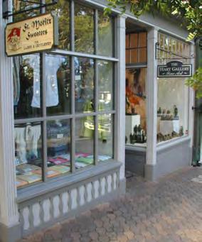

47 Architectural Standards - Frontage Types, cont'd D C B A FORECOURT SHOP FRONT GALLER ARCADE R.O.W. R.O.W. R.O.W. R.O.W. Illustrative Photo Illustrative Photo Illustrative Photo Illustrative Photo Illustrative Photo Illustrative Photo Illustrative Photo Illustrative Photo T R A N S I T Z O N I N G C O D E 4:30


48 T R A N S I T Z O N I N G C O D E : Architectural Standards - Frontage Types Sec Arcade Frontage Type (a) Arcades are facades with an attached colonnade, that is covered by upper stories. This type is ideal for retail use, but only when the sidewalk is fully absorbed within the arcade so that a pedestrian cannot bypass it. For Building Code considerations, this frontage type cannot cover the public right-of-way with out a permanent encroachment permit. 1. Configuration. A great variety of arcade designs are possible, but the following shall apply: a. The height and the proportions of the arcade shall correspond to the facade consistent with the architectural style of the building. b. A minimum of 12 feet clear in all directions. Soffits, columns/arches shall be treated consistent with the architecture of the building c. Along primary frontages, the arcade shall correspond to storefront openings and: i. Spacing between openings along the right-of-way shall be 10 feet. ii. Primary frontage storefront openings shall be at least 10 feet tall and comprise 65% of the 1st floor wall area facing the street and not have opaque or reflective glazing. iii. Storefronts shall be a minimum of 10 feet to a maximum of 16 feet tall. d. A bulkhead shall transition between the opening(s) and the adjacent grade. The bulkhead shall be between 18 inches and 36 inches tall (aluminum storefront or spandrel panel shall not substitute for a bulkhead). e. A minimum of 2 feet and maximum of 4 feet clearance from curb and face of arcade (except at curb extensions for intersections). 2. Elements f. Awnings and signs shall be located at least 8 feet above the adjacent sidewalk and may project for the width of the sidewalk at a rate of 6 inches per each foot above 8 feet to a maximum encroachment of 4 feet (see applicable zone for "encroachments"). Illustrative Photo: Arcade Sec Gallery Frontage Type (a) Galleries are colonndes that are attached to storefronts projecting over the sidewalk/walkway. 1. Configuration A great variety of gallery designs are possible, but the following shall apply: a. The height and the proportions of the gallery shall correspond to the facade consistent with the architectural style of the building b. A minimum of 12 feet wide clear in all directions. Soffits, columns/arches shall be treated consistent with the architecture of the building c. Along primary frontages, the arcade shall correspond to storefront openings and: i. Spacing between openings along the right-of-way shall be a minimum of 10 feet. ii. Primary frontage storefront openings shall be at least 10 feet tall and comprise 65% of the 1st floor wall area facing the street and shall not have opaque or reflective glazing. iii. Storefronts shall be minimum 10 feet to a maximum of 16 feet tall. d. A bulkhead shall transition between the opening(s) and the adjacent grade. The bulkhead shall be between 18 inches and 36 inches tall (aluminum storefront or spandrel panel shall not substitute for a bulkhead). e. A minimum of 2 feet and a maximum of 4 feet clearance from curb and face of arcade (except at curb extensions for intersections). 2. Elements f. Awnings and signs shall be located at least 8 feet above the adjacent sidewalk and may project for the width of the sidewalk at a rate of 6 inches per each foot above 8 feet to a maximum encroachment of 4 feet (see applicable zone for "encroachments"). Illustrative Photo: Gallery Sec Shopfront Frontage Type (a) Shopfronts are facades placed at or close to the right-of-way line, with the entrance at side walk grade. This type is conventional for retail frontage and is commonly equipped with cantilevered shed roof(s) or awning(s). Recessed storefronts are also acceptable. The absence of a raised ground floor precludes residential use on the ground floor facing the street, although such use is appropriate above. 1. Configuration A great variety of shopfront designs are possible, but the following apply: a. A minimum of 12 feet clear to a maximum of 18 feet tall, as measured from the adjacent sidewalk. b. The corresponding storefront(s) opening(s) along the primary frontage shall comprise at least 65% of the 1st floor wall area facing the street and not have opaque or reflective glazing. c. Storefronts may be recessed from the frontage line by up to 10 feet. d. A bulkhead shall transition between the opening(s) and the adjacent grade. The bulkhead shall be between 18 inches and 36 inches tall (aluminum storefront or spandrel panel may not substitute for a bulkhead) 2. Elements e. Awnings and signs shall be located at least 8 feet above the adjacent sidewalk and may project for the width of the sidewalk at a rate of 6 inches per each foot above 8 feet to a maximum encroachment of 4 feet. f. Signage shall not project within 2 feet of the adjacent curb face(s). g. Awnings shall only cover storefronts and openings so as to not cover the entire facade. Illustrative Photo: Shopfront 4:31 T R A N S I T Z O N I N G C O D E


49 Architectural Standards - Frontage Types, cont'd a R.O.W Parcel Setback Line b b e c b e c b c b c R.O.W e d R.O.W b a b Axonometric Diagram: Arcade Plan Diagram: Arcade Section Diagram: Arcade R.O.W Parcel Setback Line R.O.W a b e R.O.W b e c b c b c e d b Axonometric Diagram: Gallery Plan Diagram: Gallery Section Diagram: Gallery R.O.W Parcel Setback Line a c e R.O.W Axonmetric Diagram: Shopfront e c a d b R.O.W b e Plan Diagram: Shopfront b a a f Section Diagram: Shopfront e e d f c e c b T R A N S I T Z O N I N G C O D E 4:32
 Forecourt is a semi-public exterior space partially within the shopfront, gallery or arcade frontage that is partially surrounded by a building and also opening to a")


50 T R A N S I T Z O N I N G C O D E : Architectural Standards - Frontage Types Sec Forecourt Frontage Type (a) Forecourt is a semi-public exterior space partially within the shopfront, gallery or arcade frontage that is partially surrounded by a building and also opening to a thoroughfare forming a court. The court is suitable for gardens, outdoor dining, vehicular drop-off and utility off-loading.. 1. Configuration A great variety of forecourt designs are possible, but the following shall apply: a. A minimum of 10 feet deep clear, maximum of 40 feet deep clear. b. A minimum of 20 feet wide and a maximum of 50% lot frontage. c. The forecourt may also be raised from the sidewalk, creating a small retaining wall at the property line with entry steps to the forecourt, but shall not exceed 3 feet from the adjacent sidewalk grade. d. Storefronts shall be between 10 feet and 16 feet tall, as measured from the adjacent walkway. e. The corresponding storefront(s) opening(s) along the primary frontage shall be at least 65% of the 1st floor wall area and shall not have opaque or reflective glazing. f. A bulkhead shall be required. The bulkhead shall be 24 inches minimum, 36 inches maximum (aluminum storefront or spandrel panel shall not be substituted for a bulkhead). 2. Elements g. Minimum clearances for signs and awnings shall be 8 feet from sidewalk for vertical clearances and the width of the side walk for horizontal clearances. Illustrative Photo: Forecourt Sec Stoop Frontage Type (a) Stoops are an elevated entry pad that corresponds directly to the building entry. The stoop has stairs placed close to the frontage line on a building and the ground story elevated from the sidewalk, securing privacy for the windows and front rooms. This type is suitable for ground-floor residential uses with short setbacks. This type may be interspersed with the shopfront frontage type. A porch or shed roof may also cover the stoop. 1. Configuration A great variety of stoop designs are possible, but the following shall apply: a. A minimum of 4 feet deep clear. a1. Stoops without porches or roofs may encroach up to 50 percent of required building setback depth unless specified otherwise in zone standards. b. A minimum 4 feet wide. c. Stoops shall be at grade or raised to transition into the building. In no case shall the ground story be elevated more than 3 feet above the adjacent sidewalk. d. Stoops shall correspond directly to the building entry(s). 2. Elements e. Fences or walls defining the stoop or front setback shall not exceed 36 inches from the highest adjacent finished grade and comply with Sec Illustrative Photo: Stoop combined with Porch Sec Frontyard / Porch Frontage Type (a) Frontyards are a common frontage primarily associated with single family houses, but used with other building types depending on the context in all cases, where the facade is set back from the right of way with a front yard. An encroaching porch may also be appended to the facade. A fence or wall at the property line may be used to define the private space of the yard. The front yard may also be raised from the sidewalk, creating a small retaining wall at the property line with entry steps to the yard. 1. Configuration A great variety of porch designs are possible, but the following shall apply: a. A minimum of 6 feet deep clear. a1. Porches may encroach up to 24 inches of required building setback depth unless specified otherwise in zone standards, provided the remaining setback area shall not be less than 5 feet. b. A minimum of 12 feet wide clear for centered entry; or a minimum of 10 feet clear for assymetrical entry. c. A minimum of 10 feet tall clear. d. Porches shall be at grade or raised to transition into the building. In no case shall porches be raised more than 3 feet from the adjacent grade. 2. Elements e. Fences or walls defining the front yard shall not exceed 3 feet in height from the adjacent sidewalk and comply with Sec Retaining walls within the front yard setback cannot exceed 18 inches in height. Illustrative Photo: Frontyard / Porch 4:33 T R A N S I T Z O N I N G C O D E


51 Architectural Standards - Frontage Types, cont'd R.O.W Parcel Setback Line d e e f b a R.O.W a b R.O.W c g f e e d a Axonometric Diagram: Forecourt Plan Diagram: Forecourt Section Diagram: Forecourt R.O.W Parcel Setback line a1 a1 a a1 d d e a1 b b R.O.W R.O.W c a Axonometric Diagram: Frontyard / Porch Plan Diagram: Stoop Section Diagram: Stoop a a1 R.O.W Parcel Setback Line a1 a1 c b a1 a d b R.O.W c R.O.W e e d a Axonometric Diagram : Frontyard / Porch Plan Diagram: Frontyard / Porch Section Diagram: Frontyard / Porch T R A N S I T Z O N I N G C O D E 4:34
 Each building shall be designed in compliance with Table AS-1, entitled Permitted Archtectural Styles by Building Type.")

52 T R A N S I T Z O N I N G C O D E : Architectural Standards: Style, Massing, Proportions, and Materials Section Architectural Styles (a) Each building shall be designed in compliance with Table AS-1, entitled Permitted Archtectural Styles by Building Type. Six architectural styles are identified as relevant to the area s history and deserving of continued use and interpretation. These styles are: Building Type Table AS-1 : Permitted Architectural Styles by Building Type A. Main St. Commercial B. Mission Revival C. Art Deco D. Folk Victorian E. Craftsman F. California Contemporary A. Tower on Podium B. Flex Block - C. Lined Block - - D. Hybrid Court E. Stacked Dwelling - - F. Courtyard Housing G. Live/Work A. Main Commercial H. Rowhouse I. Tuck-under Housing - J. Bungalow Court - K. Duplex/ Triplex/ Quadplex - L. House - = Allowed - = Not Allowed D. Folk Victorian Architectural Style Guidelines 1. Intent. In preparing these guidelines, it was determined that a framework is necessary with which to both express architectural objectives within the project area and a set of clear guidelines that provides the City and future applicants a basis for proposing and reviewing development proposals. These guidelines are not intended as a style manual but rather as a framework that appropriately represents the salient characteristics of various traditional styles for design exploration and application in projects within the plan area. It is expected that these guidelines will provide supplemental design guidance for issues not expressly stated in the Santa Ana Municipal Code. 2. Style Characteristics. The six styles are described in terms, for nine subjects, that assist the user of this Code to understand their historic precedence and prepare contemporary designs in these historic styles: 1. Base 2. Primary Walls 3. Roof-Wall Connections 4. Roof 6. Openings 7. Attached Elements 8. Massing 9. Site Definition and Landscape 5. Drainage 4:35 T R A N S I T Z O N I N G C O D E


53 Architectural Standards: Style, Massing, Proportions, and Materials, cont'd B. Mission Revival C. Art Deco E. Craftsman F. California Contemporary T R A N S I T Z O N I N G C O D E 4:36


 setback within the wall, may have their own material connection to the ground, such as")


54 T R A N S I T Z O N I N G C O D E : Architectural Style Guidelines A. Main Commercial The Main Commercial building is found on almost every pre-world War II American Main. Basically a decorated rectangular masonry box in form, one-story buildings are always commercial in use, while multi-story buildings are mixed-use with commercial ground floors. Multi-story facades are typically divided into base, body and top with the ground floor taller than the shorter upper floor which is finished by a significant parapet. The ground floor has expansive glass interrupted by structural columns with transoms to allow light to penetrate deep into the interior. Upper floor windows are smaller with vertical windows directly relating to the ground floor openings. 1. Base a. Multi-story buildings: ground floor is the base and is articulated by large storefront windows and, in some cases, walls or columns of different materials from upper floors. b. Elements (not walls) setback within the wall, may have their own material connection to the ground, such as tile, wood, and/ or cast iron. Storefront with cast iron columns Painted brick transom Ground floor as base 2. Primary Walls a. The primary walls, usually composed of brick, comprise the main body of the building s tripartite facade structure. The masonry-work can be very plain or highly decorative. b. Decorative moldings, cornices, or an applied ornament of stone or cast concrete may be used to express the vertical division between the base, the body, and the top. Single plane Commercial frontage Simple, elegant arched-brick frame 3. Roof-Wall Connections a. The roof-wall connection is the top of the facade tripartite facade composition. This top, articulated as a substantial cornice, can be formed with the same material as the rest of the wall or fashioned of complimentary materials such as stone, concrete, or metal. b. Foam moldings are expressly prohibited. Masonry cornice Parapet and wood cornice Rustic wood cornice 4:37 T R A N S I T Z O N I N G C O D E


 internal drain pipes imbedded within the")


55 Architectural Style Guidelines, cont'd 4. Roof a. Invariably flat roofs are used. Parapets are articulated as an explicit exterior wall making a visual transition to the sky through plain or elaborate profiles. b. Roofs may be accessible and be used as balconies or terraces. Parapet Roof garden Articulated parapet with integrated signage 5. Drainage a. Since these buildings typically maintain a zero setback, rainwater may be diverted away from public sidewalks in several ways: i) downspouts on the the back-side or alley-side of the building, ii) internal drain pipes imbedded within the buildings walls (visible only on rear), iii) awnings or canopies Downspout on back side of building; Awnings at commercial frontage Drainage imbedded in exterior wall 6. Openings a. Ground floor windows and doors are large and expansive, typically with a transom. b. Upper floor windows are typically grouped with a rhythm relating to the major storefront openings below. c. Upper floor windows are typically double-hung (two lites) and vertically oriented. Ground floor storefront windows Grouped second-floor windows Second-floor windows grouped in pairs 7. Attached Elements a. Awnings, canopies, and second floor balconies may extend into the public right-of-way, subject to standards on chapter 3. Such attachments provide shelter to passing pedestrians, emphasize the ground floor uses, and add interest to the box-like massing inherent to the style. Awnings at commercial frontage Canopy frontage Balcony frontage 8. Massing a. Whether one-story or multiplestory, Main Commercial buildings tend to be square or rectangular boxes. However, subtle variations in height can add interest to a a facade, emphasize important architectural features such as a building entrance, or can accentuate a corner condition. 2-story block with higher massing at center One-story Flex Block Articulated corner block 9. Site Definition and Landscape a. Since buildings are typically zero-setback and urban, planting on ground floor street-facing facades is not permitted. b. Landscape, however, is to be in internal courtyards and streetfacing forecourts. Commercial frontage Forecourt frontage Courtyard within a Flex Block T R A N S I T Z O N I N G C O D E 4:38


56 T R A N S I T Z O N I N G C O D E : Architectural Style Guidelines B. Mission Revival This architecture is derived from Spanish, Italian, Greek and North African precedents, and their extraordinary progeny in North and South America from the Colonial period, and up to The Mission Revival style is a mature and complex architectural language. Its heritage is so extensive, that when applied, it evokes a heightened sense of urbanity, and an intimate relationship with nature. 1. Base a. Exterior walls reach the ground with an expression of weight, with or without a base. b. An explicit element of base is described either as a painted band of traditional colors or an applied band of stone or cast concrete. c. Elements setback within the wall, may have their own material connection to the ground, such as tile, plaster or concrete. 2. Primary Walls a. Expressed as single-plane expanses of plaster wall. b. May be articulated by traditional moldings or applied ornament of stone or cast concrete, to describe the vertical divisions into base, body and top. c. Plaster finish shall be Santa Barbara Mission-Stucco, Humpy-Bumpy brown coat 16/20 finish with 0-3/8 variation, or fine sand finish d. Control joints allowed. Painted base with deep recess Monolithic wall and base Continuous material base or can be highlighted at corners Single plane composition Intermediate molding at base Applique at cornice 3. Roof-Wall Connections a. Exterior walls will transition into roof form by one of three devices: i) A projected wooden eave with exposed wooden rafters, ii) A plaster molding or, iii) A tile cap b. Foam moldings are expressly prohibited. Expressed rafters, broad eave Clay tile with no eave Tile on profiled parapet 4:39 T R A N S I T Z O N I N G C O D E


57 Architectural Style Guidelines, cont'd 4. Roof a. May be pitched at a 3:12 ratio and finished in Roman or Mission tile laid irregularly. b. Flat roofs are allowed and shall be articulated as an explicit exterior wall (tile may be multi-color randomly placed) visual transition to the sky. May be accessible and used as balconies or terraces. c. No bird stops allowed at end condition: must be mortar filled. Sloped tile roof Parapet with flat roof Roof as balcony behind articulated parapet 5. Drainage a. May be conducted off pitched roofs by a traditional combination of gutters and downspouts. b. Flat roofs may be drained by use of trumpet scuppers. Such roofs draining internally to the roof will need tile or ceramic scuppers on exterior walls. c. Rainwater reaching the ground may be harvested in cisterns or temporarily collected in dry wells. 6. Openings a. Deep-set (min 3 plaster return) and combined with deeper balcony, loggia, and arcade elements to generate complex building-wide vertical or horizontal compostions. b. Such compositions can be symmetrical overall, locally symmetrical or, asymmetrical. c. Shutters are the aggregate size of the associated opening. d. Double-hung or multi-pane; No aluminum or white vinyl Projecting scuppers Water retention and control Gutter and downspout Deep, recessed openings Trimmed major openings Paired, recessed openings 7. Attached Elements a. All allowable urban frontages in the project area can be expressed in terms particular to this architecture. b. A number of architectural elements such as balconies, stairs and chimneys can encroach beyond the primary exterior surface of buildings and into their setbacks, as allowed in chapter 3. Useable balconies Integral stairs Integral chimneys 8. Massing a. Volumetric compositions can be of a single primary volume offset by a variety of lesser ones. Also possible are compositions that are expressed in a single volume. b. It is common and desirable to articulate building corners on corner lots. c. Such designs can be devised at the geometric corner or adjacent to it. Vertical articulation of corner Single-volume composition Articulation of corner 9. Site Definition and Landscape a. Buildings typically collect surrounding public and private space into walled precincts consistent with their use. Forecourts, garden walls and zaguans are common. b. The landscape of gardens and courtyards heightens the spatial character of each such enclosed exterior room. Fountain as garden focus Integral 1-story wall with doorway Forecourt with entry gate T R A N S I T Z O N I N G C O D E 4:40


 Pilasters that continue beyond height of")
58 T R A N S I T Z O N I N G C O D E : Architectural Style Guidelines C. Art Deco The Art Deco style is inspired by the streamlined styling of modern technology. Characterized by volumes that step back at upper floors and long pilasters that run the entire height of the building, Art Deco s sleek and cubic forms are decorated with patterns and motifs taken from the Far East, ancient Greece and Rome, Africa, India, and Mayan and Aztec cultures. Windows typically are located between the pilasters and, between floors, are often separated by decorated transom panels. 1. Base a. Exterior walls are supported on a base composed of stone, cast concrete, glazed terra cotta tile, or glazed ceramic tile (bathroom tile is not permitted). b. The entire ground floor height may be articulated as the base of the building. Masonry base and monolithic wall Marble base Ground floor as base 2. Primary Walls a. Exterior walls may be constructed of cast concrete or plaster. b. Pilasters running the entire height of the building should be included as part of the facade design. c. Windows shall be located between the pilasters. Stone Plaster and metal Glazed Terra Cotta 3. Roof-Wall Connections a. Exterior walls shall extend beyond the roof level and form a parapet that is configured in one of three ways: i) Pilasters that continue beyond height of interstitial walls, ii) Walls that continue beyond height of the pilasters, iii) Wall and pilaster that reach to same height. b. Decorated metal, ceramic tile, or glazed terra cotta transoms may be incorporated as part of parapet. Column extensions with metal transoms Plaster wall extensions with metal columns Undulating parapet 4:41 T R A N S I T Z O N I N G C O D E


 Decorative cap Corner stepped tower 5.")


59 Architectural Style Guidelines, cont'd 4. Roof a. In most cases, roofs should be flat with the exterior walls extending beyond the roofline to form parapet walls. b. Towers with whimsical roofs are permitted. Flat roof (lower volume) and sloped roof (upper volume) Decorative cap Corner stepped tower 5. Drainage a. To preserve the stylized lines of the Art Deco facades, roof drainage should located within walls of the buiding itself and therefore not visible on the facade. b. Where external scuppers and downspouts are utlized, they should be located on the side or rear facades. Sloped roofs without gutters Scupper and downspout on building side Gutter with downspout into wall 6. Openings a. Windows shall be situated between pilasters and shall be recessed. b. Windows shall be multi-paned and be vertical in orientation. c. Finely crafted, metal window grates are permitted. d. Metal or tile transom panels between windows on consecutive floors are encouraged, but not requried. Simple trim with operable shutters Recessed metal window with metal transom Recessed double-hung with metal decorative transoms 7. Attached Elements a. Architectural elements such as balconies and awnings must be designed and assembled of finelycrafted metal. These elements may encroach into the building s setbacks. b. Metal window grilles are permitted. Decorative metal awnings Metal window grille and metal balcony Punched metal letter signage 8. Massing a. Upper stories should step back, particularly for tall buildings. b. Pilasters should run the entire height of the building. Stepped-back volumes Stepped-back volumes Higher volume at corner 9. Site Defintion and Landscape a. Buildings may be situated in a zerosetback urban condition. b. Buildings may also utilize the following frontages: front yard, porch, forecourt, arcade or storefront. Storefront with awnings Porches Storefront T R A N S I T Z O N I N G C O D E 4:42


60 T R A N S I T Z O N I N G C O D E : Architectural Style Guidelines D. Folk Victorian The Folk Victorian style is characterized by vertically proportioned masses clad in wood, stone, masonry or metal composed of vertically narrow openings. Original horizontal storefronts provide a more urban grade gesture to the street while the remaining massing is concealed behind a tall facade. Structural elements such as columns, braces, etc., are often the same as the decorative elements. Typically, this style emphasizes a street-facing front with the rest of the building often being very simple in composition and decoration. Roofs are typically hidden behind prominent facades and/or parapets. Where visible, roofs are simple and finished in metal or composition shingles. 1. Base a. Exterior walls reach the ground with or without a base. b. Where present, the base is described as an applied band of wood, corrugated metal, or cast concrete, stone such as granite. 2. Primary Walls a. Expressed as single-plane expanses of wood or metal siding. The street-facing facade is typified by decorative elements such as window molding, cornices, lighting, and signage. b. Commercial: stick-frame storefront ; Residential: wood shingle c. Primarily horizontal siding or vertical board and batten. d. Smooth siding (wood or cementitious: no T-111) Raised panel base Corrugated siding to grade Wood plank siding to grade Painted wood Painted horizontal wood siding Decorative metal siding 3. Roof-Wall Connections a. The front facade is typically articulated as a decorated flat plane capped by a simple cornice supported by decorative brackets. The eve condition of side facade is articulated in a similar manner. b. Balcony ceilings will be constructed of wooden rafters and finished in wood planking. b. Foam moldings are expressly prohibited. Parapet with cornice and brackets Parapet with cornice and brackets Gable with attic vents and combination of shingle and horizontal siding 4:43 T R A N S I T Z O N I N G C O D E


61 Architectural Style Guidelines, cont'd 4. Roof a. Primary roof tends to be hidden by the street-facing parapet. b. Can be sloped or flat. Sloped roofs may be clad in metal or wood shingles. Composition shingle roof Sloped metal roof Parapet 5. Drainage a. May be conducted off pitched roofs by a traditional combination of gutters and downspouts. b. Rainwater reaching the ground may be harvested in cisterns or temporarily collected in dry wells. Scupper with downspout Gutter and downspout Gutter and downspout along column 6. Openings a. Windows and doors are framed with wood trim. b. Windows are multi-paned and vertical in orientation. c. Ground floor primarily glazed with transoms over storefronts; Upper floors glazed with smaller, vertical openings. Commercial storefronts Parapet details Double-hung windows on second floor 7. Attached Elements a. A number of decorated architectural elements such as porches, balconies, awnings, and bay windows can encroach beyond the primary exterior surface of buildings and into their setbacks. b. Arcades and galleries can extend also into the front setback. c. Columns are highly articulate, trimmed or capped. Awning with braces Arcade with signs Projecting bay windows 8. Massing a. Tend to have one primary facade that faces the street and is articulated as a decorated flat plane. b. Can be one- or two-story and tend to have a street-facing architectural bias. Intersecting volumes with corner focus Two-story ends with one-story middle Two-story with porch and balcony 9. Site Definition and Landscape a. Buildings can situated in a zerosetback, urban condition where landscaping is limited to planted pots. b. Buildings can also have a front yard, arcade, forecourt or face a courtyard. Patio Forecourt Informal planters and rain barrels T R A N S I T Z O N I N G C O D E 4:44


62 T R A N S I T Z O N I N G C O D E : Architectural Style Guidelines E. Craftsman This style was initiated in the Midwest and successfully applied to the widely varying California climate. It carries strong asian and swiss influences and was most popular from 1900 to Buildings are composed of horizontal, single- and twostory volumes. An additional floor may be concealed within the volume of the roof. In its most simple form, it is a wood box surrounded by various attached elements. Walls are typically horizontally placed wood siding, shingles or board-and-batten, with a foundation base and piers in river stone, brick or stucco. Rafter tails and porch columns are exposed, smooth, woodwork. Windows and doors are vertical in proportion, trimmed in wood. Roofs are composed of shallow sloped gabled forms, and made of wood or asphalt shingles with broad overhangs and eaves. 1. Base a. Craftsman houses invariably rest upon a base of concrete, stone, or brick. b. Stone is largest at the bottom and smallest at the top reflecting the natural stacking of the material. c. The lower floor may be stucco (20-30 fine sand finish) with the upper floor(s) clad in wood or shingle siding. Combination stone and brick base Concrete base Masonry and stone base 2. Primary Walls a. Walls shall show no more than two materials along any vertical section of the building, with no more than 90% of the total wall surface in one material. Single family detached houses are exempt. b. Piers are a minimum of 6 x6 if wood posts, and 18 x18 if stone or stucco. c. Stone is largest at the bottom and smallest at the top. Siding above painted plaster Unpainted siding above painted plaster Painted shingles above painted lap siding 3. Roof-Wall Connections a. Wide eaves with exposed rafters b. Wood braces may be used. c. Min 3 overhang d. Decorative, spaced boards to vent attics Brace and exposed rafters Structural elements as decoration Large overhangs 4:45 T R A N S I T Z O N I N G C O D E

. b.")

 Roofs parallel to street Dormer window with pitched")


63 Architectural Style Guidelines, cont'd 4. Roof a. Principal gables are between 3:12 and 4:12, and shed slopes are less than the principal slope (between 2:12 and 6:12). b. Dormers may be used to provide light and air to rooms in the attic space. c. Heavy timber throughout in lookouts and brackets (6x8 min) Roofs parallel to street Dormer window with pitched roof Dormer with flap-up roof 5. Drainage a. May be conducted off pitched roofs by a traditional combination of gutters and downspouts. b. Rainwater reaching the ground may be harvested in cisterns or temporarily collected in dry wells. c. Downspouts are painted or copper and typically round or square. Gutter and downspout Downspout Gutter and downspout 6. Openings a. Window openings should be oriented vertically, although several windows may abut to form a horizontal overall opening. b. Window lites may be divided into equal increments or be divided on a portion of a window (such as the upper portion of a double-hung or casement window: 4 over 1, 3 over 1) Vertical openings Ganged vertical openings Paired openings composed horizontally 7. Attached Elements a. Porches, chimneys, and trellises can encroach beyond the primary exterior surface of buildings and into their setbacks. b. Tapered, square columns c. Deep porches to block sun and provide shade to interiors. Front Porch Chimney Porte-cochere 8. Massing a. 3rd story always concealed in roof with dormers b. 2-story with 1-story components attached such as porches or veranda. c. 1-story simple house forms with 1-story components attached such as porches or veranda. Intersecting gables with porch Horizontal volumes, projected upper floor Hip with wrap-around verandah 9. Site Definition and Landscape a. Buildings typically face a front yard. b. Garden walls of rounded stone and/or clinker brick, brick are common. c. Trellis and other woodwork define outdoor porches and patios. Walls composed of natural materials to blend into landscape Trellis as entry Natural materials with accented gate T R A N S I T Z O N I N G C O D E 4:46


, plaster, corrugated metal, cast concrete, or concrete block.")


64 T R A N S I T Z O N I N G C O D E : Architectural Style Guidelines F. California Contemporary The California Contemporary style, the architectural analog of California Cuisine, reinterprets the modernist tradition with a local and eclectic flair. The style tends to emphasize massing over structural articulation and is characterized by interlocking volumes of different colors and materials. Architectural elements such as awnings, balconies, and trellises are appended to the volumes, often occurring in the interstitial spaces between volumes. Roofs may be flat with parapets, sloped, barrel-shaped, domed, or a combination thereof. 1. Base a. Exterior walls reach the ground with or without a base. b. Where present, the base is articulated as a band of stone, concrete block, cast concrete, or corrugated metal. c. The entire ground floor height may be articulated as the base. Concrete block base Ground floor as concrete base No base 2. Primary Walls a. Expressed as single-plane expanses of wood, cementitious, or metal siding (no T-111), plaster, corrugated metal, cast concrete, or concrete block. These various materials may be used in conjunction with one another. Painted Hardiplank siding Cast concrete Plaster combined with siding 3. Roof-Wall Connections a. The parapet of flat-roofed volumes may be articulated in a variety of ways: with a cornice, without a cornice, with a receding cornice. b. Sloped roofs may or may not may have overhangs. For roofs with sloped overhangs, exposed rafters are encouraged. c. Wood braces may be used. Parapet with cornice Parapet with receding cornice Overhang 4:47 T R A N S I T Z O N I N G C O D E


 must be designed and assembled of")


65 Architectural Style Guidelines, cont'd 4. Roof a. Roofs may be sloped, barrel-shaped, flat, or a combination thereof. Sloped roofs shall be clad in metal. Sloped metal roof Metal barrel roof Parapet 5. Drainage a. Downspouts may be utilized as decorative vertical elements and facade accents. b. Scuppers may be used to provide shadowed effects on flat facade surfaces. c. Drainage components should be metal. Scupper and downspout Scupper and downtspout Scuppers and downspouts 6. Openings a. Windows should be manufactured of quality materials such as metal or wood. b. Window openings may be either framed or unframed. c. Windows should be multi-paned and be vertical in orientation. Projecting corner window Metal window with metal transom Bay window 7. Attached Elements a. Architectural elements (balconies, trellises, awnings, and bay windows) must be designed and assembled of finely-crafted metal or wood. These elements may encroach into the building s setbacks. b. Arcades and galleries may also extend into the front setback. Awnings with braces Canvas Awning Trellis 8. Massing a. In order to avoid monolithic buildings of the same continuous height, buildings should be composed of interlocking volumes of differing heights and widths. b. Though repetition of building volumes is permitted, the repetition should not be overbearing. Volumes of differing height, width, color, and material Repetitive interlocking volumes of differing height and width Interlocking volumes and planes 9. Site Defintion and Landscape a. Buildings may be situated in a zerosetback, urban condition where landscaping is limited to planted pots or planters. b. Buildings may also utilize the following frontages: front yard, arcade, or forecourt. c. Creative solutions to landscaping atop garage podiums should be sought. Landscaped Driveway Landscape over concrete podium Raised planters T R A N S I T Z O N I N G C O D E 4:48
66 T R A N S I T Z O N I N G C O D E : Sign Standards Division 5. On-Premise Signs Sec Purpose and intent. These sign regulations are intended to appropriately limit the placement, type, size, and number of signs allowed within the Specific Development 84, and to require the proper maintenance of signs. The purposes of these limitations and requirements are to: (a) Avoid traffic safety hazards to motorists, bicyclists, and pedestrians, caused by visual distractions and obstructions; (b) Promote the aesthetic and environmental values of the community by providing for signs that do not impair the attractiveness of the City as a place to live, work, and shop; (c) Provide for signs as an effective channel of communication, while ensuring that signs are aesthetically designed and proportioned in relation to adjacent structures and the structures to which they are attached; and (d) Safeguard and protect the public health, safety, and general welfare. Sec Application of division. (a) The regulations of this division apply only to signs located in the Transit Zoning District. No person shall install or display any sign which does not comply with the standards set forth in this division, and no permit shall be issued for any such sign. The provisions of this section shall be applied in conjunction with Chapter 41, Article XI, On-Premise Signs of this code, provided however, in the event of a conflict between the provisions within this section and the remainder of the City of Santa Ana Sign Ordinance as outlined in Chapter 41, Article XI, On-Premise Signs, the provisions of this Division shall apply. (b) This article does not apply to the following sign and advertising displays: (1) Any billboard or other off-premise sign regulated by Article XII of the SAMC; (2) Any sign located in the public right-of-way and installed or maintained by the public works agency of the city of by any other public entity having legal authority to maintain signs. (3) Any sign located within a building or enclosed area and designed to be viewed primarily by persons inside of such building or enclosed area. Sec General provisions and definitions (a) A planned sign program is required for all buildings with two (2) or more commercial tenants prior to the erection or installation of any sign (1) Sign permit application and planned sign program applications shall be submitted in a manner prescribed by Article XI of the SAMC. (2) In addition, a color and lettering board also shall be submitted with each application for a sign permit. (b) The following definitions shall apply: (1) Alley/Passage means a sign that is mounted to or painted on facades fronting an alley or passage. (2) Awning means a pedestrian-oriented sign that is mounted on top of a horizontal awning parallel to the sidewalk. (3) Awning/Valence means a pedestrian-oriented sign that is applied directly to the awning s valence either through fabric or other acceptable material/ paint. (4) Color and lettering board means an exhibit drawn to scale that shows the lettering style, colors to be used (by name, sample and/or stock number of local manufacturer), dimensions, lighting characteristics, layout, and content of any proposed sign. (5) Freestanding means a pedestrian-oriented sign that is located within the front yard and projects or hangs from a post not to exceed 5 feet in height. (6) Marquee means a sign that projects from the façade to express a figural design and message to motorists and pedestrians. (7) Pole Sign means a sign supported by a single support the width of which is less than fifty (50) percent of the longest dimension of the sign. (8) Projecting means a pedestrian-oriented sign that is mounted near or at the sidewalk, perpendicular to the building so that the sign is viewed from the sidewalk. (9) Second story tenants means the distinct leasable space above the ground floor tenant space separated from others by floor to ceiling walls, and with a separate door or access point onto a street. (10) Wall sign means a sign that is mounted directly to or painted within the sign band, lintel or other allowed location on the shopfront so that the sign is viewed by both pedestrian and motorist. (11) ard/porch means a pedestrian-oriented sign that is attached to the porch and hangs or is otherwise suspended between columns supporting the porch roof. The porch sign is prominent within a bay created by the porch columns without obstructing view from inside the building or from the porch (c) Second story tenants are limited to window or projecting signs only. (d) Animated and moving signs and variable intensity, blinking or flashing signs, are only permitted when placed on a historic building and the sign corresponds to the historic character and architectural style of the building. (e) In addition to the prohibited signs contained within Article XI, the following signs are also hereby prohibited: (1) A sign burned, cut, or otherwise marked on or affixed to a rock, tree, or other natural feature. (2) No sign is permitted for tenants above the second floor. (3) Cabinet signs. (4) A sign painted directly on a building, except for historically significant and alley/passage signs. Sec Sign Standards. (a) In Table 1, entitled Permitted Signs Types by Frontage, the allowed sign types are identified per the range of frontage types in the Transit Zoning Code, except residential buildings which do not include non-residential uses which shall be regulated as follows: (1) Residential buildings with four of less dwelling units are not allowed signs. (2) Residential buildings are permitted wall and yard/porch sign types if occupied by more than four dwelling units. (b) Number of signs: In Table 2 entitled Permitted Sign Placement establishes the number of signs allowed per building. Only one sign per storefront is permitted per elevation. Logos and identification symbols shall be considered signs and shall conform to all provisions of this division. (c) Sign area and height. The maximum sign area and height for each permitted sign type is established by Table 3 entitled Requirements by Sign Type. (d) Sign location requirments. Each sign shall be located in compliance with Table 2 entitled Requirements by Sign Type and the following requirements. (1) On-premise signs required. Each sign shall be located on the same site as the subject of the sign, except as otherwise allowed by this Article and at a minimum display the name of the business. (e)sign setback requirements. Each sign shall comply with the building setback and encroachment requirements of the applicable zoning district, except for an approved freestanding sign, which shall be subject to the following setback standards: (1) Freestanding signs shall be set back a minimum of 4 feet from the front and street side property lines. (2) A freestanding sign shall be located only in a landscaped planter, with such planter not less than 4 feet in any direction from the edge of the planter to the sign. The planning manager may reduce the amount of required landscaping for freestanding signs on sites with legal nonconforming landscaped setbacks. (3) No freestanding sign shall be located in the triangular area(s) measured 15 feet by 15 feet where a driveway enters onto a street, or in any other area which may obstruct the vision of motorists so as to create a safety hazard. (f) Placement on a building. No sign shall be placed so as to interfere with the operation of a door or window. Signs should not be located so that they cover prominent architectural features of the building, including, but not limited to, transoms, prismatic glass, insignias, or any other architectural ornamentation. 5:1 T R A N S I T Z O N I N G C O D E


67 Sign Standards, cont'd Projecting Sign Projecting Sign Window Sign Window Sign Projecting Sign Wall-Mounted, Individual letter sign ard/porch Sign Marquee Sign Wall-Mounted Neon Sign Wall-Mounted Sign with individual letters Freestanding Sign Table 1: Permitted Sign Types by Frontage Frontage Type Frontyard/ Sign Type Stoop Forecourt Shopfront Gallery Arcade Porch A. ard/porch Marquee Sign B. Freestanding C. Projecting -- D. Wall/Mounted Above: Illustrative photos of allowed sign types E. Awning F. Awning/Valence G. Marquee H. Alley/Passage = Allowed -- = Not Allowed T R A N S I T Z O N I N G C O D E 5:2
68 T R A N S I T Z O N I N G C O D E : Sign Standards Sec Sign design. No sign permit shall be issued for a sign which does not comply with the following: (a) Color. (1) Colors on signs and structural members shall be harmonious with one another and relate to the dominant colors of the buildings on the site. Contrasting colors may be utilized if the overall effect of the sign is still compatible with building colors. (b) Design and construction. (1) Signs shall be consistent with the architectural design and proportions of the building it is attached to. (2) Signs shall be constructed of permanent materials and shall be permanently attached to the ground, a building, or another structure by direct attachment to a rigid wall, frame, or structure. (3) All signs and their supporting structures shall be so enclosed as to provide against their infestation by birds and vermin. (4) Signs shall not contain exposed cabinets or raceways. (5) Each permanent sign shall be designed by a professional (e.g., architect, building designer, landscape architect, interior designer, or others whose principal business is the design, manufacture, or sale of signs), or who are capable of producing professional results. (6) Each permanent sign shall be constructed by persons whose principal business is building construction or a related trade including sign manufacturing and installation, or others capable of producing professional results. The intent is to ensure public safety, achieve signs of careful construction, neat and readable copy, and durability, to reduce maintenance costs and prevent dilapidation. (c) Materials and structure. (1) Sign materials (including framing and supports) shall be representative of the type and scale of materials used on the site where the sign is located. Sign materials shall be consistent with those used on the buildings on the site and any other signs on the site. (2) No sign shall include reflective material. (3) Materials for permanent signs shall be durable and capable of withstanding weathering over the life of the sign with reasonable maintenance. Durable materials include but are not limited to the following: Wood, metal, acrylic or plexiglass and neon, and shall exclude foam, regardless of density. (4) The size of the structural members (e.g. columns, crossbeams, and braces) shall be proportional to the sign panel they are supporting. (5) Individual letters shall be incorporated into the building design, rather than a sign with background and framing other than the structure wall. (d) address. The review authority may require that a sign include the street address of the site, where it determines that public safety and emergency vehicle response would be more effectively served than if the street address were displayed solely on one or more buildings on the site. (e) Copy design guidelines. The City does not regulate the message content (copy) of signs; however, the following are principles of copy design and layout that can enhance the readability and attractiveness of signs. Copy design and layout consistent with these principles is encouraged, but not required. (1) Sign copy should relate only to the name and/or nature of the business or commercial center. (2) Permanent signs that advertise continuous sales, special prices, or include phone numbers, etc. should be avoided. (3) Information should be conveyed briefly or by logo, symbol, or other graphic manner. The intent should be to increase the readability of the sign and thereby enhance the identity of the business. (4) The area of letters or symbols should not exceed 50 percent of the background area, unless otherwise stated in Table 5C. (f ) Sign lighting. Sign lighting shall be designed to minimize light and glare on surrounding rights-of-way and properties. (1) External light sources shall be directed and shielded so that they do not produce glare off the site, on any object other than the sign. (2) Sign lighting shall not blink, flash, flutter, or change light intensity, brightness, or color. (3) Colored lights shall not be used at a location or in a manner so as to be confused or construed as traffic control devices. (4) Neither the direct nor reflected light from primary light sources shall create hazards for pedestrians or operators of motor vehicles. (5) For energy conservation, light sources shall be hard-wired fluorescent or compact fluorescent lamps, or other lighting technology that is of equal or greater energy efficiency. Incandescent lamps are prohibited except, when used in signs of historic character as part of the architectural design. Sec Sign Maintenance (a) Each sign and supporting hardware, including temporary signs and awning signs, shall be maintained in good repair and functioning properly at all times. Any damage to a sign or its illumination, including the failure of illumination shall be repaired within a maximum of 14 days from the date of damage or failure. (b) A repair to a sign shall be of materials and design of equal or better quality as the original sign. (c) A sign that is not properly maintained and is dilapidated shall be deemed a public nuisance, and may be abated in compliance with the Santa Ana Municipal Code. (d) When an existing sign is removed or replaced, all brackets, poles, and other supports that are no longer required shall be removed and the surface it was attached to repaired and painted to match the building. Sec Major development identification signs. Freestanding signs for developments occupying one acre or more may develop one additional freestanding sign with the following standards: (a) There shall be a minimum of one hundred (100) feet of separation between any freestanding signs. (b) No freestanding sign structure shall exceed five (5) feet in height and forty (40) square feet in area. (c) The size of one (1) face of the sign shall not exceed ninety (90) per cent of the sign structure. (d) The copy area of the sign shall not exceed seventy-five (75) per cent of the face of the sign. (e) The sign copy shall be limited to the business name, address, and/or identification logo. (f) Style must be consistent with the architecture of the main building and compatible with the surrounding historical structures. (g) Pole signs are not permitted. Sec Preservation of existing historic signs. (a) Historically significant painted wall signs shall be retained or recreated when possible. (b) Mounted signs announcing the name of a business no longer in existence at the sign's location and having historical significance may be salvaged and relocated. (c) All architectural signage in place on the building announcing the original or historic name of the building, year of construction or insignias shall remain in place and shall not be removed, altered or covered under any circumstances. (d) Historic signage shall not be calculated as part of the overall signage permitted pursuant to this division. Sec Building identification sign. Building identification signs shall comply with the following standards: (a) There shall be no specific size requirements, but building identification signs shall be sized proportionately to the building being identified and to the sign area in which it is located. 5:3 T R A N S I T Z O N I N G C O D E
69 Sign Standards, cont'd (b) Building identification signs may contain the name of a building or describe its function but may not identify any individual tenant of the building or any products sold. (c) Building identification signs shall not be lit. (d) Building identification signs may be made of non-illuminated individual letters applied to the building face, may be engraved into the building's material, or may be low-relief. Sec Building directory sign. A directory sign identifying businesses above the ground level shall comply with the following standard: (a) Must be located at the ground level and adjacent to the entry point for the upper levels. (b) No more than one (1) directory sign per ground level entrance. (c) The area of the directory sign shall not exceed six (6) square feet. (d) The directory sign may only identify the names of businesses above the ground level. (e) Letter height shall not exceed two (2) inches. Sec Service entry wall sign. (a) Must be located adjacent to the ground level service entrance. (b) No more than one (1) service entry wall sign per business. (c) The area of the service entry sign shall not exceed four (4) square feet. (d) The service entry sign cannot face a public street. Sec Special sale signs. Temporary signs announcing special sales in shall comply with the following standards: Sec Window Signs Signs painted directly on the window surface, including showcase and glass-paned doors, shall comply with the following standards: (a) Letters shall not exceed nine (9) inches in height or cover more than twenty-five (25) percent of a window area and shall not exceed a maximum size of twenty (20) square feet. (b) Window signage is limited to no more than one (1) window area, including street facing windows and windows in entry doors, except that businesses with street frontages between seventy-six (76) and one hundred and fifty (150) feet can have one (1) additional window sign and that businesses with street frontages over one hundred and fifty (150) feet can have one additional window sign. (c) Window signage is allowed for ground floor and second floor tenants only, with windows facing street frontage. (d) Prismatic glass or glass block, including glass transoms, may not have a sign applied to it. Signs on transoms immediately over entry doors and contained within the door frame are allowed and shall not exceed twenty-five (25) percent of the window area. (e) For windows above the first floor, window signs shall consist of individually painted letters, gold leaf letters or neon as specified below. (f) Any vacuum tube sign lit by neon gas shall comply with the following standards: (1) Letters shall not exceed nine (9) inches in height and sign area is limited to four (4) square feet. (2) Any letter style is permitted as long as letters are continuous. Painted-out spaces between letters are not permitted. (3) Neon bands may be used only to frame the sign but must be contained within the allowable sign area. (a) This type of sign is only allowed the downtown zone. (b) No more than two (2) temporary signs per business are permitted. (c) Each sign shall not exceed three (3) square feet individually, nor more than six (6) square feet collectively. (d) Such signs must be confined to lower corners of windows. (e) Such signs may be posted for no more than fourteen (14) days during any ninety-day period. Sec Credit card and trading stamp signs. Signs announcing credit card acceptance shall comply with the following standards: (1) No more than three (3) such signs are allowed for each business. (2) Such signs shall not exceed one (1) square foot individually nor three (3) square feet collectively. (3) Such signs are permitted only in ground level windows. Sec Construction Signs. Signs pertaining to construction activity shall comply with the following standards: (1) The sign face shall not exceed sixteen (16) square feet in size. (2) The signs shall not be placed more than eight (8) feet in height when freestanding or attached to a fence and shall not be placed above the first floor when affixed to a building wall. (3) Signs must be removed within thirty (30) days after issuance of an occupancy permit for the building. T R A N S I T Z O N I N G C O D E 5:4


 Marquee -- (H) Alley/Passage -- 1.")
 ard/porch -- (B) Freestanding -- (C) Projecting (D) Wall/Mounted (E) Awning (F)")
70 T R A N S I T Z O N I N G C O D E : Table 2 - Permitted Sign Placement The diagrams below identify the allowed sign types and requirements by the various conditions of frontage, as allowed by the zone in which the parcel is located. KE Building Allowed sign location subject to Table 5C Allowed -- Not Allowed FRONTARD/PORCH FRONTAGE STOOP FRONTAGE FORECOURT FRONTAGE Illustrative Photo: ard/porch Sign shown Illustrative Photo: Projecting Sign shown Illustrative Photo: Projecting Sign and Window Sign shown Alley/Passage H D A, F B A,C,D,F G G C,D,E,F Illustrative Plan Diagram: Allowed Placement Illustrative Plan Diagram: Allowed Placement Illustrative Plan Diagram: Allowed Placement Note: Corner Lots are allowed for one the following signs: D, or F Note: Corner Lots are allowed one for the following signs: C, D, or F Note: Corner Lots are allowed for the following signs: C, D, and E or F G G D D D D B F A F A C E,F C D E,F D C Illustrative Section Diagram: Allowed Placement Illustrative Section Diagram: Allowed Placement Illustrative Section Diagram: Allowed Placement Subject to the requirements in Table 5c Subject to the requirements in Table 5c Subject to the requirements in Table 5c 1. Placement Requirements Sign Type Allowed (A) ard/porch (B) Freestanding (C) Projecting -- (D) Wall/Mounted (E) Awning -- (F) Awning/Valence (G) Marquee -- (H) Alley/Passage Placement Requirements Sign Type Allowed (A) ard/porch (B) Freestanding -- (C) Projecting (D) Wall/Mounted (E) Awning -- (F) Awning/Valence (G) Marquee -- (H) Alley/Passage Placement Requirements Sign Type Allowed (A) ard/porch -- (B) Freestanding -- (C) Projecting (D) Wall/Mounted (E) Awning (F) Awning/Valence (G) Marquee (H) Alley/Passage 5:5 T R A N S I T Z O N I N G C O D E


 Wall/Mounted (E) Awning (F) Awning/Valence (G) Marquee (H)")
 Wall/Mounted (E) Awning -- (F) Awning/Valence (G) Marquee (H)")

71 Table 2- Permitted Sign Placement, cont'd SHOPFRONT FRONTAGE GALLER FRONTAGE ARCADE FRONTAGE Illustrative Photo: Projecting Sign Shown Illustrative Photo: Projecting Sign Shown Illustrative Photo: Projecting Sign Shown Alley/Passage H Alley/Passage H Alley/Passage H G C,D,E,F C,D,G F C,D,G F Illustrative Plan Diagram: Allowed Placement Illustrative Plan Diagram: Allowed Placement Illustrative Plan Diagram: Allowed Placement Note: Corner Lots are allowed for the following signs: C, D, and E or F Note: Corner Lots are allowed for the following signs: C, D, F Note: Corner Lots are allowed for the following signs: C, D, F G G G D D D E F C F C F C Illustrative Section Diagram: Allowed Placement Illustrative Section Diagram: Allowed Placement Illustrative Section Diagram: Allowed Placement Subject to the requirements in Table 5c Subject to the requirements in Table 5c Subject to the requirements in Table 5c 1. Placement Requirements Sign Type Allowed (A) ard/porch -- (B) Freestanding -- (C) Projecting (D) Wall/Mounted (E) Awning (F) Awning/Valence (G) Marquee (H) Alley/Passage 1. Placement Requirements Sign Type Allowed (A) ard/porch -- (B) Freestanding -- (C) Projecting (D) Wall/Mounted (E) Awning -- (F) Awning/Valence (G) Marquee (H) Alley/Passage 1. Placement Requirements Sign Type Allowed (A) ard/porch -- (B) Freestanding -- (C) Projecting (D) Wall/Mounted (E) Awning -- (F) Awning/Valence (G) Marquee (H) Alley/Passage T R A N S I T Z O N I N G C O D E 5:6


72 T R A N S I T Z O N I N G C O D E : Table 3 - Requirements by Sign Types The following diagrams illustrate the key characteristics and requirements for the allowed sign types in the Plan area. A ard/ porch B Freestanding ard/porch: A pedestrian-oriented sign that is attached to the porch and hangs or is otherwise suspended between columns supporting the porch roof. The sign is prominent within a bay created by the porch columns without obstructing view from inside the building or from the porch. Freestanding: A pedestrian-oriented sign that is located within the front yard and projects or hangs from a post not to exceed 5 feet in height. E Awning (Top-Mounted) F Awning/ Valence Awning (top mounted): A pedestrian-oriented sign that is mounted on top of a horizontal awning parallel to the sidewalk. Awning /valence: A pedestrian-oriented sign that is applied directly to the awning s valence either through fabric or other acceptable material/paint. 5:7 T R A N S I T Z O N I N G C O D E


73 Table 3- Requirements by Sign Types, cont'd C Projecting D Wall-mounted ` Business Sign Business Sign Projecting: A pedestrian-oriented sign that is mounted near or at the sidewalk, perpendicular to the building so that the sign is viewed from the sidewalk. Wall: A sign that is mounted directly to or painted within the sign band, lintel or other allowed location on the shopfront so that the sign is viewed by both pedestrian and motorist. G Marquee H Alley / Passage Marquee: A sign that projects from the façade to express a figural design and message to motorists and pedestrians. Alley/Passage: A sign that is mounted to or painted on facades fronting an alley or passage. TABLE 3 REQUIREMENTS B SIGN TPE KE A B C D ard/ porch Freestanding Projecting Wall E F G H Awning / Valence Awning Marquee Alley/Passage Sign Face Width 36" max 36" max 48" max 75% width of storefront 20 max [1] 20 max [1] 6 max [2] 200 max Sign Face Height 24" max 24" max 16" max 18"min -36"max 18" max 18" max - 50' max Sign Copy Area 5 sq. ft per side (2 sides) 8 sq. ft per side (2 sides) 5 sq. ft per side (2 sides) 24 max, up to 1 sq ft per linear ft of store frontage 24 max, up to 1 sq ft per linear ft of store frontage Max 50% of '1' Max 75% of '1' Max 75% of '1' Clear from Sidewalk 8 min 12" min 8 min - 8 min 8 min 12 min 3 min Clear from Grade - 5' max Space - 12" max Feature/logo max 20% of '3' max 20% of '3' max 20% of '3' max 20% of '3' max 6 sq ft max 50% of 1 max 75% of 1 Murals Allowed 8 Distance from Sidewalk or Curb - 4' min from sidewalk within 2 of curb - within 2 of curb within 2 of curb Thickness " max " max 0 [3] Extension above roofline ' max - 11 Alignment may align with corner or be placed anywhere on wall - Signs Per Building 1 max 1 max 1 per business with a storefront 1 per business with a storefront 1 per awning 1 per awning 1 max 2 max for building with frontage along alley or passage Key -- Standard not applicable [1] within storefront bay; [2] to within 2 of curb [3] May encroach up to 6 inches, when the bottom of the sign is at least 18 feet above the curb T R A N S I T Z O N I N G C O D E 5:8


74 alley access where occurs alley access where occurs T R A N S I T Z O N I N G C O D E : Network Concepts Subdivision Guidelines: Blocks and Guidelines A. Purpose 1. This chapter establishes guidelines for maintaining and adding to Santa Ana's walkable block and street network. The procedure for subdividing land is intended to provide for the urban infrastructure of small and walkable blocks, and an interconnected and human-scaled network of streets punctuated by open space of varying types. In addition, this chapter allows for the threedimensional parcelization of buildings in response to ownership patterns. The following guidelines apply to all property within the boundaries of the SD. Table 6A: Block Requirements Block Type [1] L: Block Length D: Block Depth Orthagonal: Square or Min Max Min Max Rectangular LWD Lot Width/Depth [2] As specified per building type in Table 4A B. Guidelines 1. Applicability. These guidelines apply to all subdivisions of land, whether to legally divide or consolidate lots, or to create 'design lots' and are subject to the review and approval of the City of Santa Ana. Trapezoidal: Irregular LWD Lot Width/Depth [2] Min Max Min Max 500 Avg. for Avg. for longest sides longest sides As specified per building type in Table 4A 2. Pedestrian-Oriented Building Design. Existing and new blocks within the boundaries of the SD must facilitate pedestrian-oriented building design. All development must be designed in compliance with the following guidelines, in addition to all other applicable provisions of this code, the Citywide design guidelines and the SAMC. [1] All blocks to comply with Santa Ana requirements for intersection spacing [2] The lot is primarily for design purposes and may be made permanent through the regular process for lot line adjustments, or parcel and/or tract maps. a. Buildings shall be designed on lots consistent with the requirements for building types in Sec through 2039 of this code; L D b. Buildings shall be designed to have fronts and backs, with front facades containing primary building entrances and facing streets and/or open space; c. Buildings may be subdivided vertically in response to ownership patterns. The diagram below, shows that buildings may be subdivided vertically in any number of configurations provided that the applicable requirements of condominium parcelization are met to the satisfaction of the City of Santa Ana. 3. Design objectives. Each site subject to these requirements shall be designed to be divided into smaller blocks with: Internal streets, where appropriate to connect with off-site streets and/or to create a series of smaller, walkable blocks; Primary LWD LWD Block Length Block Depth LWD LWD LWD Service alleys (public or private) within the new blocks; Parcels within the block(s) for the purpose of facilitating pedestrian-oriented building design; Orthogonal Block Requirements Diagram Side street Buildings, as allowed, corresponding to parcels with their entrances on bordering streets. 4. Subdivision requirements. Each site subject to these requirements shall be designed in compliance with the following standards, and to achieve the objectives identified above. L Block Depth D Block Requirements. The requirements in Table 6A apply to any new block or to the modification of existing blocks in the area regulated by the Code. LWD Block Length Blocks of various designs and functions are allowed as identified in the diagram at right and per the corresponding standards in Table 6A. Primary 5. s / Rights-of-Way All blocks shall be designed per the allowable street types, in substantial compliance with and as identified on Figure 7-1, Network Concepts. All streets shall be accessible to the public. LWD 6. Lots. All buildings shall be designed to an individual lot as required in Table BT-1. Note: As it relates to this section of the Code, the lot is for design purposes and may be made permanent through the regular process for parcel or tract maps. Lot width and depth shall be determined as set forth in Section LWD Trapezoidal Block Requirements Diagram Side street LWD 7. Access requirements. After the initial subdivision of a site into blocks and streets, it may become necessary to adjust alley or other right-of-way access. In this case, the following shall apply as identified below and in Table 6A.1: a. Realignment of right(s) of way. Existing or approved rights-of-way may be realigned subject to City of Santa Ana approval such that the resulting block and private property meet the requirements of this section and the applicable building type requirements (Sections through 2039). b. Existing Alley-Access. In all cases, blocks with alleys shall maintain such access. Existing or approved alley-access may be modified subject to City of Santa Ana approval through realignment, (shift, deflection, etc.) provided the realigned alley results in a minimum 100 feet of net developable lot depth on both sides of the realigned alley. Table 6A.1: Alley Access Options Existing alley access Realignment - Deflected Alley Realignment - Shifted Alley 6:1 T R A N S I T Z O N I N G C O D E


75 Table 6B: Illustrative Sequence - Applying subdivision standards to achieve pedestrian-scaled buildings This series of diagrams identifies the sequence of creating and maintaining walkable and multi-modal blocks to be developed in a variety of ways per the provisions of this code. This information illustrates the intent of the subdivision standards combined with the building type standards Sec through 2039 and provides direction on how to generate new blocks with lots that receive pedestrian-scaled buildings. Illustrative Diagram Illustrative Example A Step 1: Existing Site PROPERT BOUNDAR STREET Sites that are not already in compliance with Figure 7.1 ( Network Plan) shall be subdivided further to create additional blocks per the requirements of Subdivision Guideline) and Network Concepts. For sites already in compliance with Figure 7.1 or as adjusted per Section 7.1B, the requirements to introduce streets and alleys do not apply. STREET STREET B Step 2: Introduce s PROPERT BOUNDAR STREET 1. Sites being subdivided into additional blocks shall introduce streets from the coneptual street types in the Network Concepts and comply with the applicable block-size requirements. Adjustments to the conceptual street network are allowed per the provisions of section 7.1B. STREET NEW STREET 2. The Regulating plan must be adjusted to account for new public r.o.w STREET C Step 3: Introduce Alleys PROPERT BOUNDAR STREET Vehicular access to blocks and their individual lots is allowed primarily by alley or side street with certain zones allowing primary street vehicular access. The intent is to maintain the integrity and continuity of the streetscape without interruptions such as driveway access. Therefore, unless the lot(s) is encouraged to take access from the street per the Urban Standards For the Zone, or if the lot(s) takes access via a side street, the introduction of rear service thoroughfares such as alleys is required. STREET NEW STREET STREET D Step 4: Introduce Lots 1. Based on the type(s) of blocks created and the street(s) that they front, lots are introduced on each block to correspond with the selected building type(s) from Section Sec through These lots are for the purpose of design and reflect the minimum area needed to effectively design corresponding pedestrian-oriented buildings. The permanence of the lot lines is not required by these standards. PROPERT BOUNDAR STREET STREET NEW STREET 2. A Building Type is identified for each lot. 3. Review applicable Building Type requirements to design buildings. STREET E Step 5: Introduce Projects PROPERT BOUNDAR STREET Each lot is designed to receive a building per the allowable building types in Sections through 2039 and is arranged to suit the particular organization of buildings desired for each particular block. The allowable building types then are combined with the allowable frontage types to generate a particular neighborhood form and character consistent with the purpose of the Code. STREET NEW STREET This Page: This series of diagrams identifies the sequence of creating walkable and multi-modal blocks to be developed in a variety of ways per the provisions of this code. This section also provides direction on how to break down large parcels to receive appropriately scaled buildings. STREET T R A N S I T Z O N I N G C O D E 6:2


 comply with the City's requirements of the Subdivision Guidelines; b.")
76 T R A N S I T Z O N I N G C O D E : Network Concepts Network Concepts A. Purpose This chapter indentifies the various street types deployed to assemble the street network for the plan area. The guidelines of this section work with the subdivision guidelines to: 1. provide the information with which to modify existing streets, 2. provide the information on with which to maintain existing streets that are not proposed to change. 3. produce new, variable blocks and streets, The diagram at right identifies the conceptual improvements to the existing thoroughfare network for the Specific Plan area. B. Alignment and Adjustments. This chapter establishes the guidelines for interpreting or modifying the alignments of streets as shown Figure 7-1 ( Network Concepts). alignments may be shifted as follows: 1. Lateral Adjustment. Such adjustments and/or the modification of one end point of a street or street segment are allowed provided that: a. The resulting block(s) complies with the requirements of the Subdivision Guidelines. b. The resulting intersections comply with the city's requirements for intersection alignment; c. Adjustments less than 2 times the streets' r.o.w. width may be approved administratively; d. Adjustments in excess of 2 times the street's r.o.w. width require planning commission approval. 2. Additional s. s may to be added to the network subject to the administrative approval of the City of Santa Ana as follows: a. That the resulting block(s) comply with the City's requirements of the Subdivision Guidelines; b. That the additional street(s) is from the conceptual types as identified in Figure 7-1 or a new street type per subsection C below; c. That the applicable safety requirements are addressed to the satisfaction of the City of Santa Ana. C. New Types. New street types beyond those identified in Figure 7-1 maybe allowed by the City of Santa Ana if the new street is determined by the City of Santa Ana to be generally consistent with one of the allowed types in Table 7A. D. Future Development. Any future or planned development adjacent or near the railroad right-of-way shall be planned with the safety of the rail corridor in mind. This includes considering pedestrian circulation/destinations with respect to railroad right-of-way. Figure 7-1 Network Plan ft n Light Specifications The examples below represent the allowed types of street lights for the plan area and shall be installed per the applicable Public Works Agency standards. Waste Can Type: RS-12, 36 gallons (Victor Stanley) or equal as approved by City PBA and PWA. Bench Type: CR-138, 4 feet long (Victor Stanley) or equal as approved by City of Santa Ana Standard Plan 1126 'I' 14' - 6" height to center of lamp refer to City specifications for details City of Santa Ana Standard Plan 1126 'A' 18' - 0" height to center of lamp refer to City specifications for details Furniture The above represent the allowed types of street furniture for the Plan area. 6:3 T R A N S I T Z O N I N G C O D E

77 Network Concepts, cont'd Key Condition/Direction Existing - remain R.O.W. Varies Design Speed [1] Varies Existing - remove Varies Varies Existing - revise Varies Varies New Varies Varies Begin 1-way Varies Varies End 1-way Varies Varies Left: The Circulation Element identifies five types of streets/highways for the City-wide circulation system. Within the Plan area, three types exist: Major Arterials, Primary Arterials, and Secondary Arterials. Local streets occur within each of these types and comprise the balance of the network. The existing circulation system and pattern of blocks is shown with the direction for implementing the three types of arterials within the Plan area. Above: The circulation system with the planned improvements and connections to both implement the Circulation Element and respond to the needs and desired contexts throughout the plan area. Key Circulation Element Reference Code Type [2] Major Arterial [1] Major & Primary Arterial [1] Local Primary & Secondary Arterial [1] Local Local Local BV A M U1 U2 R1 R2 AL P N E BV-1 Boulevard Avenue Main Urban 1 Urban 2 Residential 1 Residential 2 Alley / Driveway Paseo (conceptual) New Traffic Signal Existing Traffic Signal Section Number Type [1] As identified in the Circulation Element of the Santa Ana General Plan [2] Refer to Table 7A for guidelines regarding specific streets R.O.W. Varies Varies Varies Varies Varies Varies Varies 20' Varies Right: The list of street types to be used in the plan area and their cross-reference to the Circulation Element. T R A N S I T Z O N I N G C O D E 6:4
 PARKING... one side Santa Ana Blvd.")


78 T R A N S I T Z O N I N G C O D E : Table 7A: Concepts for Specific s Santa Ana Boulevard - French to Broadway A-3 Existing condition MOVEMENT... free MEDIAN... none TRAFFIC LANES/POTENTIAL TRANSIT ; one way (westbound) PARKING... one side Santa Ana Blvd. from French to Broadway would be experienced as a moderately paced, free moving one-way arterial characterized by tall palm trees in tree wells along wide sidewalks. lights poles would be at pedestrian scale. furniture, such as streetlights, benches, waste receptacles and periodical racks would be in a style complimentary to the overall streetscape. Parking would be provided on one side of the street. The street could accommodate multiple modes of transportation choices, which could include a fixed guideway, such as a streetcar, buses, automobiles and bicycles. Plan / Section Diagram Santa Ana Boulevard - French to Mortimer A-4 Existing condition MOVEMENT... free MEDIAN... none TRAFFIC LANES/POTENTIAL TRANSIT BIKE LANES TO BE STUDIED AS PART OF FIXED GUIDEWA. PARKING... one side Santa Ana Blvd. from French to Mortimer would be experienced as a moderately paced, free moving arterial characterized by canopy trees in continuous planters visually separating the vehicular traffic from the pedestrian traffic on sidewalks. lights poles would be at pedestrian scale. furniture, such as streetlights, benches, waste receptacles and periodical racks would be in a style complimentary to the overall streetscape. Parking would be provided on one or both sides of the street. The street could accommodate multiple modes of transportation choices, which could include a fixed guideway, such as a streetcar, buses, automobiles and bicycles. Plan / Section Diagram 6:5 T R A N S I T Z O N I N G C O D E


79 Table 7A: Concepts for Specific s, cont'd Santiago Avenue A-5 Existing condition MOVEMENT... free MEDIAN... 10'; planted with striped turn lane TRAFFIC LANES... 4; 2 each way PARKING... none Santiago Avenue from Washington to 6th would be experienced as a moderately paced, free moving arterial characterized by canopy trees in tree wells along wide sidewalks. A new landscaped median could be installed. light poles would be at pedestrian scale. furniture, such as streetlights, benches, waste receptacles and periodical racks would be in a style complimentary to the overall streetscape. Parking and bike lanes could be provided on one or both sides of the street, depending on future studies and MPAH compliance. Plan / Section Diagram Fourth (Main) M Existing condition TPE... main street MOVEMENT... slow MEDIAN... none TRAFFIC LANES... 1 each way PARKING... both sides, diagonal Fourth from Ross to French would be experienced as a slow paced, slow moving street with intense and mixed-use streetscape. Tall and narrow trees in tree wells are located along wide sidewalks that could accommodate commercial outdoor activity, such as outdoor dining as well as active pedestrian circulation. lights poles would be at pedestrian scale. furniture, such as streetlights, benches, waste receptacles, bike and periodical racks would be in a style complimentary to the overall streetscape. The street could accommodate a variety of on-street parking options in concert with a multi-modal transit design, which could include a fixed guideway, such as a streetcar, buses, automobiles and bicycles. Plan / Section Diagram T R A N S I T Z O N I N G C O D E 6:6


80 T R A N S I T Z O N I N G C O D E : Table 7A: Concepts for Specific s Fifth - Broadway to Main U1-1 Existing condition MOVEMENT... free MEDIAN... none TRAFFIC LANES... 3; one way PARKING... one side Fifth from Broadway to Main would be experienced as a moderately slow paced, free moving urban street characterized by canopy trees in tree wells along wide sidewalks that could accommodate an intense and mixed-use streetscape. lights poles would be at pedestrian scale. furniture, such as streetlights, benches, waste receptacles and periodical racks would be in a style complimentary to the overall streetscape. Parking would be provided on one side of the street depending on the locally preferred alternative for the fixed guideway. The street could accommodate multiple modes of transportation choices, which could include buses, automobiles and bicycles. Plan / Section Diagram Fifth - Main to Minter U1-2 Existing condition MOVEMENT... free MEDIAN... none TRAFFIC LANES... 3, 1-way PARKING... one side Fifth from Main to Minter would be experienced as a moderately slow paced, free moving urban street characterized by canopy trees in tree wells along wide sidewalks that could accommodate an intense and mixed-use streetscape. lights poles would be at pedestrian scale. furniture, such as streetlights, benches, waste receptacles and periodical racks would in a style complimentary to the overall streetscape. Parking would be provided on one side of the street depending on the locally preferred alternative for the fixed guideway. The street could accommodate multiple modes of transportation choices, which could include buses, automobiles and bicycles. Plan / Section Diagram 6:7 T R A N S I T Z O N I N G C O D E


81 Table 7A: Concepts for Specific s, cont'd Fourth - French to Grand Avenue U1-3 Existing condition MOVEMENT... free MEDIAN... Lanscaped TRAFFIC LANES... 4; 2 each way PARKING... none Fourth from French to Grand Avenue would be experienced as a moderately paced, free moving secondary arterial characterized by canopy trees in tree wells along wide sidewalks. A new landscaped median could be installed. light poles would be at pedestrian scale. furniture, such as streetlights, benches, waste receptacles and periodical racks would in a style complimentary to the overall streetscape. Parking would be provided on both sides of the street depending on the locally preferred alternative for the fixed guideway and compliance with MPAH. Plan / Section Diagram Standard U1-4 Existing condition MOVEMENT... free MEDIAN... none TRAFFIC LANES... 2; 1 each way PARKING... none Standard from Fourth to Sixth would be experienced as a moderately free moving arterial street characterized by canopy trees in tree wells along wide sidewalks that could accommodate an intense and mixed-use streetscape. lights poles would be at pedestrian scale. furniture, such as streetlights, benches, waste receptacles and periodical racks would in a style complimentary to the overall streetscape. Parking may need to be eliminated on one or both sides of the street. Plan / Section Diagram T R A N S I T Z O N I N G C O D E 6:8

82 T R A N S I T Z O N I N G C O D E : Table 7A: Concepts for Specific s Urban 1 U1-5 Example MOVEMENT... free MEDIAN... none TRAFFIC LANES... 2; 1 each way BIKE LANES... 2; 1 each way PARKING... both sides, parallel The Urban 1 type would be experienced as a moderately slow paced, free moving urban street characterized by canopy trees in tree wells along wide sidewalks. lights poles would be at pedestrian scale. furniture, such as streetlights, benches, waste receptacles and periodical racks would in a style complimentary to the overall streetscape. Parking would be provided on both sides of the street. Plan / Section Diagram 6:9 T R A N S I T Z O N I N G C O D E


83 Table 7A: Concepts for Specific s, cont'd Third - Ross to Broadway U2-1 Existing condition MOVEMENT... free MEDIAN... none TRAFFIC LANES... 2, 1 each way BULBOUTS... mid-block - 250' spacing MEDIAN... none PARKING... both sides Third from Ross to Broadway would be experienced as a slow paced, slow moving urban street characterized by canopy trees in tree wells along wide sidewalks. lights poles would be at pedestrian scale. furniture, such as streetlights, benches, waste receptacles and periodical racks would in a style complimentary to the overall streetscape. Parking lanes would be provided on both sides of the street. Plan / Section Diagram Second - West of Broadway U2-2 Existing condition MOVEMENT... slow MEDIAN... none TRAFFIC LANES... 2; 1 each way BULBOUTS... end of block PARKING... both sides Second, west of Broadway would be experienced as a slow paced, slow moving urban street characterized by canopy trees in tree wells along wide sidewalks. lights poles would be at pedestrian scale. furniture, such as streetlights, benches, waste receptacles and periodical racks would in a style complimentary to the overall streetscape. Parking lanes and bulbouts at the end of the block would be provided on both sides of the street. Plan / Section Diagram T R A N S I T Z O N I N G C O D E 6:10


84 T R A N S I T Z O N I N G C O D E : Table 7A: Concepts for Specific s Bush U2-3 Existing condition MOVEMENT... slow MEDIAN... none TRAFFIC LANES... 2; 1 each way BULBOUTS... mid-block - 250' spacing PARKING... both sides Bush would be experienced as a slow paced, slow moving urban street characterized by canopy trees in tree wells along wide sidewalks. lights poles would be at pedestrian scale. furniture, such as streetlights, benches, waste receptacles and periodical racks would in a style complimentary to the overall streetscape. Parking lanes would be provided on both sides of the street as needed. Plan / Section Diagram Urban 2 U2-4 Example MOVEMENT... slow MEDIAN... none TRAFFIC LANES... 2, 1 each way PARKING... both sides, parallel The Urban 2 type would be experienced as a slow paced, slow moving narrow urban street characterized by canopy trees in tree wells along wide sidewalks. lights poles would be at pedestrian scale. furniture, such as streetlights, benches, waste receptacles and periodical racks would in a style complimentary to the overall streetscape. Parking would be provided on both sides of the street. Plan / Section Diagram 6:11 T R A N S I T Z O N I N G C O D E


85 Table 7A: Concepts for Specific s, cont'd Urban 2 - One Way U2-5 Example MOVEMENT... slow MEDIAN... none TRAFFIC LANES... 1; 1 way PARKING... none The one-way Urban 2 would be experienced as a slow paced, slow moving narrow urban street adjacent to a linear open space. This street type is characterized by canopy trees in tree wells along a wide sidewalk on one side and a linear park on the other side of the street. lights poles would be at pedestrian scale. furniture, such as streetlights, benches, waste receptacles and periodical and bike racks would in a style complimentary to the overall streetscape. Plan / Section Diagram Paseo P-1 Example MOVEMENT... n/a MEDIAN... n/a TRAFFIC LANES... n/a PARKING... n/a Any street closure is contrary to the to City s goal of providing a highly connected, multimodal circulation network, with a fine grain created by relatively small blocks. However, within the Specific Plan area, there are some streets that restrict or do not accommodate vehicular traffic. Paseos are experienced as public places designed for walking or bicycling bordered by intense urban activity, which may include outdoor dining activity. Plan / Section Diagram T R A N S I T Z O N I N G C O D E 6:12


86 T R A N S I T Z O N I N G C O D E : Table 7A: Concepts for Specific s Minter R1-1 Existing condition MOVEMENT... MEDIAN... TRAFFIC LANES... BULBOUTS... PARKING... free none 2; 1 each way mid-block - 250' spacing both sides Minter would be experienced as a moderately slow paced, free moving residential street characterized by canopy trees in continuous planters, visually separating the vehicular traffic from the pedestrian traffic on sidewalks. lights poles would be at pedestrian scale and in a style complimentary to the overall streetscape. Parking would be provided on both sides of the street. Bulbouts may be installed midblock as needed. Plan / Section Diagram Garfield R1-2 Existing condition MOVEMENT... MEDIAN... TRAFFIC LANES... BULBOUTS... PARKING... slow none 2; 1 each way mid-block - 250' spacing both sides Garfield would be experienced as a slow paced, slow moving residential street characterized by canopy trees in continuous planters, visually separating the vehicular traffic from the pedestrian traffic on sidewalks. lights poles would be at pedestrian scale and in a style complimentary to the overall streetscape. Parking would be provided on both sides of the street. Bulbouts may be installed midblock as needed. Plan / Section Diagram 6:13 T R A N S I T Z O N I N G C O D E


87 Table 7A: Concepts for Specific s, cont'd Poinsettia R1-3 Existing condition MOVEMENT... free MEDIAN... none TRAFFIC LANES... 2; 1 each way BULBOUTS... mid-block - 250' spacing PARKING... both sides Poinsettia would be experienced as a moderately slow paced, free moving residential street characterized by canopy trees in continuous planters, visually separating the vehicular traffic from the pedestrian traffic on sidewalks. lights poles would be at pedestrian scale and in a style complimentary to the overall streetscape. Parking would be provided on both sides of the street. Bulbouts may be installed midblock as needed. Plan / Section Diagram Sixth R1-4 Existing condition MOVEMENT... free MEDIAN... none TRAFFIC LANES... 2; 1 each way BULBOUTS... mid-block - 250' spacing PARKING... both sides Sixth would be experienced as a moderately paced, free moving residential street characterized by canopy trees in continuous planters, visually separating the vehicular traffic from the pedestrian traffic on sidewalks. lights poles would be at pedestrian scale and in a style complimentary to the overall streetscape. Parking would be provided on both sides of the street. Bulbouts may be installed midblock as needed. Plan / Section Diagram T R A N S I T Z O N I N G C O D E 6:14


88 T R A N S I T Z O N I N G C O D E : Table 7A: Concepts for Specific s Lincoln R1-5 Existing condition MOVEMENT... free MEDIAN... none TRAFFIC LANES... 2; 1 each way PARKING... one side Lincoln would be experienced as a moderately slow paced, free moving residential street characterized by canopy trees in tree wells along the west sidewalk only. lights poles would be at pedestrian scale and in a style complimentary to the overall streetscape. Parking would be provided on one side of the street. Plan / Section Diagram Residential 1 R1-6 Example MOVEMENT... free MEDIAN... none TRAFFIC LANES... 2; 1 each way PARKING... both sides, parallel The Residential 1 would be experienced as a moderately paced, free moving residential street characterized by canopy trees in continuous planters, visually separating the vehicular traffic from the pedestrian traffic on sidewalks. lights poles would be at pedestrian scale and in a style complimentary to the overall streetscape. Parking and bulbouts at the end of the block would be provided on both sides of the street. Plan / Section Diagram 6:15 T R A N S I T Z O N I N G C O D E


89 Table 7A: Concepts for Specific s, cont'd Lacy R2-1 Existing condition MOVEMENT... slow MEDIAN... none TRAFFIC LANES... 2; 1 each way BULBOUTS... mid-block - 250' spacing PARKING... both sides Lacy would be experienced as a slow paced, slow moving residential street characterized by canopy trees either in continuous planters, visually separating the vehicular traffic from the pedestrian traffic on sidewalk, or in wells along the sidewalk. lights poles would be at pedestrian scale and in a style complimentary to the overall streetscape. Parking would be provided on both sides of the street. Bulbouts may be installed midblock as needed. Plan / Section Diagram Garfield R2-2 Existing condition MOVEMENT... slow MEDIAN... none TRAFFIC LANES... 2; 1 each way BULBOUTS... mid-block - 250' spacing PARKING... both sides Garfield would be experienced as a slow paced, slow moving residential street characterized by canopy trees in tree wells along the sidewalk. lights poles would be at pedestrian scale and in a style complimentary to the overall streetscape. Parking would be provided on both sides of the street. Bulbouts may be installed midblock as needed. Plan / Section Diagram T R A N S I T Z O N I N G C O D E 6:16


90 T R A N S I T Z O N I N G C O D E : Table 7A: Concepts for Specific s Residential 2 R2-3 Example MOVEMENT... slow MEDIAN... none TRAFFIC LANES... 2; 1 each way PARKING... both sides, parallel - intermittent / light use The Residential 2 would be experienced as a slow paced, slow moving residential street characterized by canopy trees in continuous planters, visually separating the vehicular traffic from the pedestrian traffic on sidewalks. lights poles would be at pedestrian scale and in a style complimentary to the overall streetscape. Parking and bulbouts at the end of the block would be provided on both sides of the street. Plan / Section Diagram Residential 2 R2-4 Example MOVEMENT... slow MEDIAN... none TRAFFIC LANES... 2; 1 each way PARKING... east (park side) only The Residential 2 would be experienced as a slow paced, slow moving residential street adjacent to an open space. This street type is characterized by canopy trees in continuous planters along a sidewalk on one side and a park on the other side of the street. lights poles would be at pedestrian scale. furniture, such as streetlights, benches, waste receptacles and periodical and bike racks would in a style complimentary to the overall streetscape. Parking would be provided on the park side of the street only. Plan / Section Diagram 6:17 T R A N S I T Z O N I N G C O D E


 2.")
91 Table 7A: Concepts for Specific s, cont'd Alley / Driveway AL-1 Example TPE... alley (note: if public, must traverse the block) MOVEMENT... yield MEDIAN... none TRAFFIC... one shared lane PARKING... none Key: The alley/driveway would be experienced as a very slow moving, traffic sharing, right of way. A - A minimum of 3 when garages face each other across alley B - 4' shoulders to be constructed with structured capacity either with suface pavers or gravel subgrade Plan / Section Diagram Typical Bulb-out Typical Mid-Block Crossing Drainage Alternate: covered curb trench using ADA- acceptable, removable steel grate. Drainage Alternate: covered curb trench using ADA- acceptable, removable steel grate. 100 ' min from nearest pedestrian crossing Minimum Criteria for Applying a Mid-block crossing includes but is not limited to the following:[1] 1. ADT of 12,000 or less (single-lane each direction) 2. ADT of 15,000 or less (multi-lanes each direction) including raised ped refuge mph or less pedestrians per hour for at least 4 hours of a typical day 5. Adequate sign-distance available for pedestrians and motorists [1] Context-Sensitive Solutions, A Recommended Practice, ITE 2006 T R A N S I T Z O N I N G C O D E 6:18
Administration Peer Review
 CHAPTER 5 : T H E C O D E STANDARDS FOR THE PRIVATE REALM 5.1.010 - Purpose This Chapter of the North Montclair Downtown Specific Plan provides detailed regulations for development and new land uses within
Article 3. SUBURBAN (S-) NEIGHBORHOOD CONTEXT
 NEIGHBORHOOD CONTEXT") Article 3. SUBURBAN (S-) NEIGHBORHOOD CONTEXT this page left intentionally blank Contents ARTICLE 3. SUBURBAN (S-) NEIGHBORHOOD CONTEXT DIVISION 3.1 NEIGHBORHOOD CONTEXT DESCRIPTION...3.1-1 Section 3.1.1
Article 3. SUBURBAN (S-) NEIGHBORHOOD CONTEXT this page left intentionally blank Contents ARTICLE 3. SUBURBAN (S-) NEIGHBORHOOD CONTEXT DIVISION 3.1 NEIGHBORHOOD CONTEXT DESCRIPTION...3.1-1 Section 3.1.1
City of Chico Title 19 Land Use & Development Regulations TND Zone
 City of Chico Title 19 Land Use & Development Regulations TND Zone Adopted by the City of Chico July 3, 2002 (Ordinance #2358) TITLE 19 LAND USE AND DEVELOPMENT REGULATIONS TABLE OF CONTENTS DIVISION VI.
Coding For Places People Love Main Street Corridor District
 Coding For Places People Love Main Street Corridor District 1) Scope a) District boundaries are assigned according to the District Boundary Map. b) The Primary Retail Corridor is assigned according to
Composition of traditional residential corridors.
 Page 1 of 7 St. Petersburg, Florida, Code of Ordinances >> PART II - ST. PETERSBURG CITY CODE >> Chapter 16 - LAND DEVELOPMENT REGULATIONS >> SECTION 16.20.060. CORRIDOR RESIDENTIAL TRADITIONAL DISTRICTS
CHAPTER COMMERCIAL AND INDUSTRIAL ZONING DISTRICTS
 Commercial and Industrial Zoning Districts 106.26.010 CHAPTER 106.26 - COMMERCIAL AND INDUSTRIAL ZONING DISTRICTS COMMERCIAL AND INDUSTRIAL ZONING DISTRICTS Sections: 106.26.010 - Purpose 106.26.020 -
Table of Contents ARTICLE 5A CHARACTER-BASED ZONING 1
 Table of Contents ARTICLE 5A CHARACTER-BASED ZONING 1 SECTION 10.5A10 GENERAL... 1 10.5A11 Purpose and Intent... 1 10.5A12 Applicability... 1 10.5A13 Compliance with Regulating Plan... 1 10.5A14 Relationship
Table of Contents ARTICLE 5A CHARACTER-BASED ZONING 1
 Table of Contents ARTICLE 5A CHARACTER-BASED ZONING 1 SECTION 10.5A10 GENERAL... 1 10.5A11 Purpose and Intent... 1 10.5A12 Applicability... 1 10.5A13 Compliance with Regulating Plan... 1 10.5A14 Relationship
Chapter DOWNTOWN ZONING DISTRICTS
 Chapter 20.14 Sections: 20.14.010 Purpose of the Downtown Zoning Districts 20.14.020 Land Use Regulations for Downtown Zoning Districts 20.14.030 Development Standards for Downtown Zoning Districts 20.14.010
Chapter CC COMMUNITY COMMERCIAL ZONES REGULATIONS
 Effective April 14, 2011 Chapter 17.35 CC COMMUNITY COMMERCIAL ZONES REGULATIONS SECTIONS: 17.35.010 Title, Intent, and Description 17.35.020 Required Design Review Process 17.35.030 Permitted and Conditionally
Article 6. GENERAL URBAN (G-) NEIGHBORHOOD CONTEXT
 NEIGHBORHOOD CONTEXT") Article 6. GENERAL URBAN (G-) NEIGHBORHOOD CONTEXT this page left intentionally blank Contents ARTICLE 6. GENERAL URBAN (G-) NEIGHBORHOOD CONTEXT DIVISION 6.1 NEIGHBORHOOD CONTEXT DESCRIPTION...6.1-1 Section
Article 6. GENERAL URBAN (G-) NEIGHBORHOOD CONTEXT this page left intentionally blank Contents ARTICLE 6. GENERAL URBAN (G-) NEIGHBORHOOD CONTEXT DIVISION 6.1 NEIGHBORHOOD CONTEXT DESCRIPTION...6.1-1 Section
4 DEVELOPMENT STANDARDS FOR
 4 DEVELOPMENT STANDARDS FOR RESIDENTIAL MIXED-USE PROJECTS This chapter presents standards for residential mixed-use projects in the Ashland-Cherryland Business District and the Castro Valley Central Business
Part 4.0 DEVELOPMENT REGULATIONS
 M A I N S T R E E T N O R T H Part 4.0 DEVELOPMENT REGULATIONS 4.1 Districts 4.2 Permitted and Prohibited Uses, Standards and Standard Specific Criteria and Other General Provisions 4.3 DPS REGULATIONS
SECTION 7. RESIDENTIAL DISTRICTS
 SECTION 7. RESIDENTIAL DISTRICTS 7.1 RESIDENTIAL DISTRICTS PURPOSE 7.2 PERMITTED AND SPECIAL USES 7.3 YARD AND BULK REGULATIONS 7.4 GENERAL STANDARDS OF APPLICABILITY 7.5 FLOOR AREA RATIO MEASUREMENT AND
Chapter MIXED USE ZONING DISTRICTS
 Page 1 of 12 Page 1/12 Chapter 17.18 MIXED USE ZONING DISTRICTS Sections: 17.18.010 Purposes. 17.18.020 Permitted, conditional and prohibited uses. 17.18.030 Bulk, 17.18.010 Purposes. A. Mixed Use Districts.
Public Review of the Slot Home Text Amendment
 Public Review of the Slot Home Text Amendment The proposed amendments to the Denver Zoning Code have been informed by the Slot Home Strategy Report. This document has been developed out of a robust process
East Side Community Meeting
 East Side Community Meeting November 29, 2017 Pam Thompson, Senior Planner Sustainable Development and Construction City of Dallas Authorized Hearing Process City Plan Commission authorized a hearing to
serving retail on the ground floor street frontage with offices and housing above and behind. Purpose and Intent: To create a vibrant pedestrian
 Community Mixed Use (CM) Zone Purpose and Intent: To create a vibrant pedestrian and bicycle-oriented commercial district with high quality public spaces and comprised of community serving retail on the
ARTICLE 5. COMMERCIAL AND OFFICE DISTRICTS 5.1 PURPOSE STATEMENTS 5.2 USES 5.3 DIMENSIONAL STANDARDS 5.4 DESIGN STANDARDS 5.5 DK DISTRICT STANDARDS 5
 ARTICLE 5. COMMERCIAL AND OFFICE DISTRICTS 5.1 PURPOSE STATEMENTS 5.2 USES 5.3 DIMENSIONAL STANDARDS 5.4 DESIGN STANDARDS 5.5 DK DISTRICT STANDARDS 5.6 CU DISTRICT STANDARDS 5.7 SW DISTRICT STANDARDS THE
City of North Richland Hills Transit Oriented Development Code
 Section 118-561. Purpose and Intent: City of North Richland Hills Transit Oriented Development Code The purpose of the Transit Oriented Development (TOD) Code is to support the development of the community
Attachment 5 - Ordinance 3154 Exhibit D (Revised for 9/15 Council Meeting) Page 1 of 7 Port Townsend Municipal Code. Chapter 17.18
 Page 1 of 7 Port Townsend Municipal Code. Chapter 17.18") Page 1 of 7 Page 1/7 Chapter 17.18 MIXED USE ZONING DISTRICTS Sections: 17.18.010 Purposes. 17.18.020 Permitted, conditional and prohibited uses. 17.18.030 Bulk, 17.18.010 Purposes. A. Mixed Use Districts.
Page 1 of 7 Page 1/7 Chapter 17.18 MIXED USE ZONING DISTRICTS Sections: 17.18.010 Purposes. 17.18.020 Permitted, conditional and prohibited uses. 17.18.030 Bulk, 17.18.010 Purposes. A. Mixed Use Districts.
Article 7. URBAN CENTER (C-) NEIGHBORHOOD CONTEXT
 NEIGHBORHOOD CONTEXT") Article 7. URBAN CENTER (C-) NEIGHBORHOOD CONTEXT this page left intentionally blank Contents ARTICLE 7. URBAN CENTER (C-) NEIGHBORHOOD CONTEXT DIVISION 7.1 NEIGHBORHOOD CONTEXT DESCRIPTION.........................
Article 7. URBAN CENTER (C-) NEIGHBORHOOD CONTEXT this page left intentionally blank Contents ARTICLE 7. URBAN CENTER (C-) NEIGHBORHOOD CONTEXT DIVISION 7.1 NEIGHBORHOOD CONTEXT DESCRIPTION.........................
Missing Middle Housing in Practice
 Missing Middle Housing in Practice Daniel Parolek Principal, Opticos Design, Inc. dan@opticosdesign.com New Partners for Smart Growth Kansas City, MO 2013 1 Bungalow Courts Missing MIddle Housing 2012
Chapter CN NEIGHBORHOOD CENTER COMMERCIAL ZONES REGULATIONS
 Chapter 17.33 - CN NEIGHBORHOOD CENTER COMMERCIAL ZONES REGULATIONS Sections: 17.33.010 - Title, intent, and description. 17.33.020 - Required design review process. 17.33.030 - Permitted and conditionally
BYLAW NO. 15/026 A BYLAW OF THE REGIONAL MUNICIPALITY OF WOOD BUFFALO TO AMEND THE LAND USE BYLAW NO. 99/059
 Attachment 2 BYLAW NO. 15/026 A BYLAW OF THE REGIONAL MUNICIPALITY OF WOOD BUFFALO TO AMEND THE LAND USE BYLAW NO. 99/059 WHEREAS Section 639 of the Municipal Government Act requires every municipality
Oak Cliff Gateway District PD 468
 Oak Cliff Gateway District PD 468 August 21, 2014 2013 Authorized Hearing Authorized Hearing September, 2013 September 12, 2013 City Plan Commission expanded boundaries to represent current Oak Cliff Gateway
CHAPTER NORTH LAKE SPECIFIC PLAN
 North Lake Specific Plan 17.34.010 CHAPTER 17.34 - NORTH LAKE SPECIFIC PLAN Sections: 17.34.010 - Purpose of Chapter 17.34.020 - Purposes of SP-1 (North Lake Specific Plan) Overlay District 17.34.030 -
City of North Richland Hills Transit Oriented Development Code
 City of North Richland Hills Transit Oriented Development Code Section 118-561. Purpose and Intent: The purpose of the Transit Oriented Development (TOD) Code is to support the development of the community
SECTION CLASSIFICATION OF ZONES For the purpose of this Code the following primary land use zoning districts are hereby established:
 ARTICLE 4 ZONING DISTRICTS SECTION 4.010 CLASSIFICATION OF ZONES For the purpose of this Code the following primary land use zoning districts are hereby established: Primary Zones Abbreviated Designation
TABLE OF CONTENTS. Chapters and Sections
 TABLE OF CONTENTS Chapters and Sections Chapter 9.02 Permits and Approvals [Addition]... 1 9.02.090 Administrative variances.... 1 Chapter [New]... 1 9.07.091 Purpose and Intent... 1 9.07.092 Applicability...
May 12, Chapter RH HILLSIDE RESIDENTIAL ZONES REGULATIONS Sections:
 May 12, 2017 Chapter 17.13 RH HILLSIDE RESIDENTIAL ZONES REGULATIONS Sections: 17.13.010 Title, intent, and description. 17.13.020 Required design review process. 17.13.030 Permitted and conditionally
DIVISION 1.3 OFFICIAL ZONING MAP
 Article 1. General Provisions Division 1.3 Official Zone Map DIVISION 1.3 OFFICIAL ZONING MAP SECTION 1.3.1 ADOPTION OF OFFICIAL MAP The digital maps created and maintained by the Department of Community
DT Downtown. a) Intent. The "downtown (DT) district" is designed for the commercial core of Lake Worth, primarily along Lake and Lucerne Avenues from
 Intent. The downtown (DT) district is designed for the commercial core of Lake Worth, primarily along Lake and Lucerne Avenues from") DT Downtown. a) Intent. The "downtown (DT) district" is designed for the commercial core of Lake Worth, primarily along Lake and Lucerne Avenues from Golfview to the Florida East Coast Railroad right-of-way.
DT Downtown. a) Intent. The "downtown (DT) district" is designed for the commercial core of Lake Worth, primarily along Lake and Lucerne Avenues from Golfview to the Florida East Coast Railroad right-of-way.
CAN TRADITIONAL ZONING ACHIEVE OUR GOALS FOR DOWNTOWN ANN ARBOR?
 TRADITIONAL ZONING TRADITIONAL ZONING CAN TRADITIONAL ZONING ACHIEVE OUR GOALS FOR DOWNTOWN ANN ARBOR? A dense, mixed use core with flexible land uses A range of housing types and costs A walkable, pedestrian-oriented
FOR SALE > MULTIFAMILY/COMMERCIAL REDEVELOPMENT OPPORTUNITY
 FOR SALE > MULTIFAMILY/COMMERCIAL REDEVELOPMENT OPPORTUNITY 2220 W. Cary Street RICHMOND, VA 23220 CURRENT PROPERTY ILLUSTRATION CONCEPTUAL ONLY (NOT PROPOSED) Property Information Zoning: R-63, Multifamily
COMMERCIAL ZONING DISTRICTS (Amended 11/13/14) Part I. C-1 Restricted Commercial District
 Part I. C-1 Restricted Commercial District") ARTICLE XI. COMMERCIAL ZONING DISTRICTS (Amended 11/13/14) Part I. C-1 Restricted Commercial District Section 152: Purpose This district is designed to accommodate commercial uses which act as a transition
ARTICLE XI. COMMERCIAL ZONING DISTRICTS (Amended 11/13/14) Part I. C-1 Restricted Commercial District Section 152: Purpose This district is designed to accommodate commercial uses which act as a transition
Sec Tier 2 principal uses and structures. The principal uses of land and structures allowed in Tier 2 are provided below subject to the
 Sec. 27-730.4.9. Tier 2 principal uses and structures. The principal uses of land and structures allowed in Tier 2 are provided below subject to the standards and limitations contained within this division.
MACK URBAN SITE 1 & 1a (VTT-72702) PROJECT DESCRIPTION (REVISED )
 PROJECT DESCRIPTION (REVISED )") MACK URBAN SITE 1 & 1a (VTT-72702) PROJECT DESCRIPTION 1114-1154 S. GRAND AVENUE, 309-321 W. 12 TH STREET, 1147-1155 S. OLIVE STREET (REVISED 2-13-14) Project Location The proposed Mack Urban Site 1 &1a
MACK URBAN SITE 1 & 1a (VTT-72702) PROJECT DESCRIPTION 1114-1154 S. GRAND AVENUE, 309-321 W. 12 TH STREET, 1147-1155 S. OLIVE STREET (REVISED 2-13-14) Project Location The proposed Mack Urban Site 1 &1a
ARTICLE 10 SPECIAL PURPOSE DISTRICTS
 ARTICLE 10 SPECIAL PURPOSE DISTRICTS Sec. 29.1000. SPECIAL PURPOSE DISTRICTS. (1) Purpose. Each Special Purpose District will appear on the City's Zoning Map as a Base Zone. The Special Purpose Districts
From Policy to Reality
 From Policy to Reality Updated ^ Model Ordinances for Sustainable Development 2000 Environmental Quality Board 2008 Minnesota Pollution Control Agency Funded by a Minnesota Pollution Control Agency Sustainable
Old Town District December 4, Purpose and Intent
 1. Purpose and Intent 1.1. Generally. The purpose of the Old Town Zoning District, hereafter known as the OT District, is to facilitate the redevelopment and preservation of the Old Town Area into a walkable,
Article 3: Specific to Zones
 Article 3: Specific to Zones Content Page # Division 3.1: Establishment and Designation of Zones 3-1 3.1.10 Purpose 3-1 3.1.20 Establishment of Zones 3-1 3.1.30 Transect Zones 3-1 3.1.40 Overlay Zones
DIVISION 7. R-6 AND R-6A RESIDENTIAL ZONES* The purpose of the R-6 residential zone is:
 Date of Draft: March 6, 2015 DIVISION 7. R-6 AND R-6A RESIDENTIAL ZONES* Sec. 14-135. Purpose. The purpose of the R-6 residential zone is: (a) To set aside areas on the peninsula for housing characterized
Camp Washington Zoning Proposed Changes 11/30/2018
 Camp Washington Zoning Proposed Changes 11/30/2018 The Camp Washington Community Board was established in 1975 to help save houses in distress, build homeownership, and generally improve the quality of
DEVELOPMENT STANDARDS FOR RESIDENTIAL PROJECTS RESIDENTIAL BUILDING TYPES: APPROPRIATE ZONES AND DENSITIES 2-1
 2 DEVELOPMENT STANDARDS FOR RESIDENTIAL PROJECTS RESIDENTIAL BUILDING TYPES: APPROPRIATE ZONES AND DENSITIES 2-1 This Chapter presents the development standards for residential projects. Section 2.1 discusses
Article IV. Terminology
 Article IV. Terminology 212-22 Purpose. Add or amend the following definitions: BUILDING HEIGHT The vertical distance measured from the average elevation of the proposed finished grade at the front of
SECTION CORRIDOR DISTRICTS
 4.0401 Purpose SECTION 4.0400 CORRIDOR DISTRICTS General Corridor District Characteristics 4.0410 Rockwood Town Center (RTC) 4.0411 Station Centers (SC) 4.0412 Corridor Multi-Family (CMF) 4.0413 Corridor
LITTLE MOUNTAIN ADJACENT AREA REZONING POLICY
 LITTLE MOUNTAIN ADJACENT AREA REZONING POLICY JANUARY 2013 CONTENTS 1.0 INTENT & PRINCIPLES...1 2.0 APPLICATION...2 3.0 HOUSING TYPES, HEIGHT & DENSITY POLICIES...3 3.1 LOW TO MID-RISE APARTMENT POLICIES...4
A New Zoning Code for a 21st Century Los Angeles
 A New Zoning Code for a 21st Century Los Angeles To create livable communities, encourage sustainable development and foster economic vitality, we need a modern and user-friendly zoning code we need to
City of Valdosta Land Development Regulations
 Chapter 206 Section 206-1 Base Zoning Districts Standards for Uses, Structures, and Property Development (B) (C) Principal Uses and Structures. Principal uses and structures permitted in each base zoning
ARTICLE C. ZONING TEXT, DISTRICT CLASSIFICATIONS AND BOUNDARIES
 ARTICLE C. ZONING TEXT, DISTRICT CLASSIFICATIONS AND BOUNDARIES Sec. 10-2054. ZONING TEXT, DISTRICT CLASSIFICATIONS AND BOUNDARIES. In order to regulate the location of structures, the height and bulk
PUD Zoning Framework
 PUD Zoning Framework PUD Zoning Framework Purpose Development Review Process Site Plan Review Process Planned Unit Developments (PUD) are tools for dealing with special situations or accomplishing certain
Chapter 9.10 Downtown Districts
 Division 2: Base and Overlay Districts Chapter 9.10 Downtown Districts 9.10.001 Incorporation of Downtown Community lan Standards and Development standards and land use designations, for the Downtown Community
ARTICLE 535. PD 535. C.F. Hawn Special Purpose District No. 3
 ARTICLE 535. PD 535. C.F. Hawn Special Purpose District No. 3 SEC. 51P-535.101. LEGISLATIVE HISTORY. PD 535 was established by Ordinance No. 23988, passed by the Dallas City Council on August 25, 1999.
DEVELOPMENT STANDARDS
 Chapter 5 DEVELOPMENT STANDARDS 501 Residential Development Standards 502 Neighborhood Commercial Standards 503 Mixed Use Standards 504 Industrial Development Standards 505 Public Use Standards 506 Open
Chapter URBAN VILLAGE ZONING DISTRICTS
 Chapter 20.16 Sections: 20.16.010 Purpose of the Urban Village Zoning Districts 20.16.020 Land Use Regulations for the Urban Village Zoning Districts 20.16.030 Development Standards & Guidelines for the
6. RESIDENTIAL ZONE REGULATIONS
 6. RESIDENTIAL ZONE REGULATIONS PART 6A PURPOSE OF CHAPTER (1) The purpose of this Chapter is to provide detailed regulations and requirements that are relevant only to residential zones and specific residential
ARTICLE 834. PD 834. PD 834 was established by Ordinance No , passed by the Dallas City Council on December 8, (Ord.
 ARTICLE 834. PD 834. SEC. 51P-834.101. LEGISLATIVE HISTORY. PD 834 was established by Ordinance No. 28070, passed by the Dallas City Council on December 8, 2010. (Ord. 28070) SEC. 51P-834.102. PROPERTY
R3 (MULTIPLE-FAMILY RESIDENCE)
") Planning and Building Agency Planning Division 20 Civic Center Plaza P.O. Box 1988 (M-20) Santa Ana, CA 92702 (714) 647-5804 R3 (MULTIPLE-FAMILY RESIDENCE) Sec. 41-258. Sec. 41-258.5. Sec. 41-259. Purpose.
Planning and Building Agency Planning Division 20 Civic Center Plaza P.O. Box 1988 (M-20) Santa Ana, CA 92702 (714) 647-5804 R3 (MULTIPLE-FAMILY RESIDENCE) Sec. 41-258. Sec. 41-258.5. Sec. 41-259. Purpose.
ZONING ORDINANCE PRESENTATION
 July 25, 2012 Village of Mundelein, Illinois ZONING ORDINANCE PRESENTATION Presented by Camiros, Ltd. GOALS FOR ORDINANCE A Zoning Ordinance that: Implements the land use policies of the Village Is understandable
Plan Dutch Village Road
 Plan Dutch Village Road Objective: The lands around Dutch Village Road are a minor commercial area that services the larger Fairview community. Maintaining the vibrancy of the area by planning for redevelopment
Bunker Hill Part II Urban Design. Specific Plan. Case No. CPC SP TABLE OF CONTENTS
 Bunker Hill Part II Urban Design Specific Plan Case No. CPC-2011-684-SP TABLE OF CONTENTS Section 1. Section 2. Section 3. Section 4. Section 5. Section 6. Section 7. Section 8. Section 9. Section 10.
Sec. 20. District and intent -- UMD, Urban Mixed-Use District.
 THE FOLLOWING DOCUMENT IS FOR INFORMATIONAL UROSES ONLY. LEASE CONTACT THE CITY OF COCOA, LANNING & ZONING DIVISION FOR COMLETE INFORMATION. THANK YOU. The provisions of this district are intended to provide
2.35 BVT G Bow Valley Trail General Commercial District [ ]
![2.35 BVT G Bow Valley Trail General Commercial District [ ]](/thumbs/94/119006025.jpg "2.35 BVT G Bow Valley Trail General Commercial District [ ]") 2.35 BVT G Bow Valley Trail General Commercial District [2014 07] 2.35.1 Purpose This district is intended to form the core of Canmore s visitor accommodation outside the resorts and provide a variety
2.35 BVT G Bow Valley Trail General Commercial District [2014 07] 2.35.1 Purpose This district is intended to form the core of Canmore s visitor accommodation outside the resorts and provide a variety
4.2 RESIDENTIAL ZONING DISTRICTS
 4.2 RESIDENTIAL ZONING DISTRICTS A. Purpose: To define regulations and standards for each residential zoning district in the City. The following sections identify uses, regulations, and performance standards
VOLUME II - APPENDIX B - BASIC ZONING ORDINANCE ARTICLE V. DISTRICT REGULATIONS
 Sec. 5.1000. Multiple-family Residential (R-5). (Ord. No. 4005, 1(Res. No. 8947, Exh. A, 55), 4-3-12) Sec. 5.1001. Purpose. This district is intended to provide for development of multiple-family residential
City of Reno October 30, 2012 Draft Midtown Zoning Text Amendments 1
 Section 18.08.405 Regional Center and Transit Corridor Overlay Districts (i) SVTC South Virginia Street Transit Corridor Overlay Zoning District. (1) Applicability. This Section 18.08.405(l)'s standards
OFFICIAL AGENDA PLANNING & ZONING COMMISSION CITY OF STARKVILLE, MISSISSIPPI
 OFFICIAL AGENDA PLANNING & ZONING COMMISSION CITY OF STARKVILLE, MISSISSIPPI WORK SESSION MEETING OF TUESDAY, OCTOBER 25, 2011 BUILDING DEPT (2 ND FLOOR), 101 E. LAMPKIN STREET, 5:30 PM I. CALL TO ORDER
Chapter DENSITY AND OPEN SPACE REQUIREMENTS
 Chapter 19.52 DENSITY AND OPEN SPACE REQUIREMENTS Sections: 19.52.010 Lot coverage Requirements generally. 19.52.020 Measurement of lot coverage. 19.52.030 Lot coverage R-15 zone. 19.52.040 Lot coverage
F l e x c o d e. T o w n o f L e l a n d, N C
 T1 T2 T3 T4 F l e x c o d e T o w n o f L e l a n d, N C T5 Town of Leland North Carolina TABLE OF CONTENTS ARTICLE 1. GENERAL TO ALL PLANS... 2 1.1 AUTHORITY... 2 1.2 APPLICABILITY... 2 1.3 INTENT...
4 LAND USE 4.1 OBJECTIVES
 4 LAND USE The Land Use Element of the Specific Plan establishes objectives, policies, and standards for the distribution, location and extent of land uses to be permitted in the Central Larkspur Specific
4-900 MILITARY PARKWAY-SYCENE CORRIDOR OVERLAY DISTRICT
 4-900 MILITARY PARKWAY-SYCENE CORRIDOR 4-901 PURPOSE AND SCOPE Ord. 3846/12-18-06 The Military Parkway Scyene Corridor is positioned centrally between the Mesquite Arena and Rodeo Entertainment District,
A APPENDIX A: FORM-BASED BUILDING PROTOTYPES
 A : A.1 Introduction Form-based prototypes are specific building types that are either encouraged or discouraged in historic multi-family residential or mixed-use neighborhoods. Their intent is to ensure
(Ord. No. 2834, 6(Exh. A), ) Chapter MIXED/MULTIUSE ZONE Purpose Uses permitted. Page 1.
, ) Chapter MIXED/MULTIUSE ZONE Purpose Uses permitted. Page 1.") Chapter 17.45 - MIXED/MULTIUSE ZONE Sections: 17.45.010 - Purpose. A. The purpose of this chapter to provide regulations that implement the goals and policies of the general plan and other similar long-range
Chapter 17.45 - MIXED/MULTIUSE ZONE Sections: 17.45.010 - Purpose. A. The purpose of this chapter to provide regulations that implement the goals and policies of the general plan and other similar long-range
ACCESSORY DWELLING UNITS IN THE SOUTHEAST SECTOR
 February 19, 2019 Staff Report to the Municipal Planning Board LDC2018-10020 Item #11 S U M M A R Y Applicant The City of Orlando ACCESSORY DWELLING UNITS IN THE SOUTHEAST SECTOR Applicant s Request Update
FOR SALE 3520 and 3533 Watson Rd, St. Louis, MO 63139
 CHURCH And SCHOOL FOR SALE MLS # 17011742 $795,000 FOR SALE 3520 and 3533 Watson Rd, St. Louis, MO 63139 Property Highlights 350+ Seat Sanctuary 40+ Car Parking Kitchen Fellowship Hall Staff Kitchen Staff
Town of Windham Land Use Ordinance Sec. 400 Zoning Districts SECTION 400 ZONING DISTRICTS
 Town of Windham Land Use Ordinance Sec. 400 Zoning Districts Sections SECTION 400 ZONING DISTRICTS SECTION 400 ZONING DISTRICTS 4-1 401 Districts Enumerated 4-2 402 Location of districts; Zoning Map 4-2
900 BURRARD STREET CD-1 GUIDELINES (BY-LAW NO. 6421) (CD-1 NO. 229) CONTENTS. 1 Application and Intent... 1
 (CD-1 NO. 229) CONTENTS. 1 Application and Intent... 1") 50 City of Vancouver Land Use and Development Policies and Guidelines Community Services, 453 W. 12th Ave Vancouver, BC V5Y 1V4 F 604.873.7344 fax 873.7060 planning@city.vancouver.bc.ca 900 BURRARD STREET
50 City of Vancouver Land Use and Development Policies and Guidelines Community Services, 453 W. 12th Ave Vancouver, BC V5Y 1V4 F 604.873.7344 fax 873.7060 planning@city.vancouver.bc.ca 900 BURRARD STREET
Article 50: Business Zones
 ARTICLE 50, Use Regulations Controlling Business Zones [Added effective 7-25-1955] 118-500. East Avenue Village District. [Amended effective 7-25-1955; 9-13-1955; 11-10-1966; 12-11-1975; 7-15-1976; 5-16-1980;
Denver Zoning Code Text Amendment #3 Slot Home Text Amendment PLANNING BOARD REVIEW REDLINE DRAFT 3/13/18
 Denver Zoning Code Text Amendment #3 Slot Home Text Amendment PLANNING BOARD REVIEW REDLINE DRAFT 3/13/18 This document contains a redlined draft of the proposed text amendments to implement the strategies
ORDINANCE NO. C 34911
 ORDINANCE NO. C 34911 AN ORDINANCE relating to Residential Zones; amending SMC sections 17C.110.020, 17C.110.030, 17C.110.100, 17C.110.205, 17C.110.220, 17C.110.245, 17C.110.310, Table 17C.110-3 and adopting
City of Coral Gables Planning and Zoning Staff Report
 City of Coral Gables Planning and Zoning Staff Report Applicant: Application: Public Hearing: Date & Time: Location: City of Coral Gables Zoning Code Text Amendment Giralda Plaza Overlay District Planning
17.13 RH HILLSIDE RESIDENTIAL ZONES REGULATIONS SECTIONS:
 Effective April 14, 2011 Chapter 17.13 RH HILLSIDE RESIDENTIAL ZONES REGULATIONS SECTIONS: 17.13.010 Title, Intent, and Description 17.13.020 Required Design Review Process 17.13.030 Permitted and Conditionally
8.5.1 R1, Single Detached Residential District
 8.5.1 R1, Single Detached Residential District The purpose of this district is to provide for residential development in the form of single detached dwellings. Dwelling, Single Detached Home Business,
Article 2. Rules of Interpretation
 Article 2. Rules of Interpretation Article 2. Rules of Interpretation Sec. 2.1. Building Types 2.1.1. Building Type Descriptions... 2-2 Sec. 2.2. Rules Applicable to all Districts 2.2.1. Site... 2-5 2.2.2.
DAVIDSON PLANNING ORDINANCE AMENDMENTS AFTER SEPTEMBER 2009 SECTION 9
 AMENDMENT ADOPTED 6/12/2012 Section 9.1.3.3.1 Wall Murals Entire Section Added: 9.1.3.3.1 Wall Murals DAVIDSON PLANNING ORDINANCE AMENDMENTS AFTER SEPTEMBER 2009 SECTION 9 Exterior wall murals are only
ARTICLE 4 - ZONING DISTRICTS
 ARTICLE 4 - ZONING DISTRICTS The following chart is a summary of the uses permitted in each zoning district with the exception of the Downtown Overlay, UMCAD and Preservation Districts. The letter "P"
ARTICLE 4 - ZONING DISTRICTS
 ARTICLE 4 - ZONING DISTRICTS The following chart is a summary of the uses permitted in each zoning district with the exception of the Downtown Overlay, UMCAD and Preservation Districts. The letter "P"
PERMITTED USES: Within the MX-1 Mixed Use Neighborhood District the following uses are permitted:
 6.25 MX-1 - MIXED USE NEIGHBORHOOD 6.25.1 INTENT: The purpose of the MX-1 Mixed Use Neighborhood District is to accommodate the development of a wide-range of residential and compatible non-residential
CITY OF SARATOGA SPRINGS ZONING ORDINANCE TABLE 1: 2.0 BASE ZONING DISTRICTS
 2.0 BASE S 2.1 INTENT To fulfill the intent and purpose of this Chapter, the following tables identify zoning districts and district intents (Table 1), districts use schedule (Table 2), and districts area
2. The modification is consistent with the objectives of this chapter.
 DRAFT February 11, 2009 BMC 20.28 Infill Housing 20.28.010 Purpose. This chapter establishes special development regulations for a series of housing forms that are different than the traditional detached
COMMERCIAL/INDUSTRIAL DEVELOPMENT GUIDELINES
 COMMERCIAL/INDUSTRIAL DEVELOPMENT GUIDELINES Planning Division Sections Chapter 17.16 Commercial, Industrial Development Standards 17.16.010 Lot Size 17.16.020 Setbacks 17.16.030 Fences, Hedges and Walls
GC General Commercial District
 Section 712. GC General Commercial District 712.1 Intent of District. It is the intent of this section that the GC Zoning District be developed and reserved for general business purposes. The regulations
Town Center South End Development Area District
 175.28 ESTABLISHMENT OF DISTRICTS. In order to carry out the purpose and intent of this chapter, the area of the is hereby divided into eighteen (18) Zoning District Classifications and one overlay zoning
DRAFT ZONING BY-LAW AMENDMENT 75 DUBLIN STREET NORTH ZC1612
 DRAFT ZONING BY-LAW AMENDMENT 75 DUBLIN STREET NORTH ZC1612 Additions to the Draft Downtown Zoning By-law D.2 zone presented to Council at a public meeting on September 12, 2016 are displayed in a text
ARTICLE III: LAND USE DISTRICTS 304 R 9 DISTRICT
 ARTICLE III: LAND USE DISTRICTS III 23 304 R 9 DISTRICT (RESIDENTIAL 9 UNITS PER ACRE) 304 1 Intent and Purpose The R 9 District is intended to implement the policies of the Comprehensive Plan for areas
ORDINANCE NO. The Board of Supervisors of the County of Ventura, State of California, ordains as follows: Section 1
 ORDINANCE NO. AN ORDINANCE OF THE VENTURA COUNTY BOARD OF SUPERVISORS AMENDING DIVISION 8, CHAPTER 1, ARTICLE 2, 5, 7, 8, 9, 11, 13 AND 19 OF THE VENTURA COUNTY ORDINANCE CODE, NON-COASTAL ZONING ORDINANCE
ARTICLE III Section COMMERCIAL OFFICE RETAIL ENTERPRISE DISTRICT
 ARTICLE III Section 3-100 COMMERCIAL OFFICE RETAIL ENTERPRISE DISTRICT Section 3-100.1 Intent. The CORE district is intended to accommodate high intensity business uses appropriate for downtown locations
UPDATE Board of Selectmen June 20, 2017
 MAPLE STREET I-1 AREA DRAFT ZONING BYLAW & DEVELOPMENT STANDARDS Town of Danvers, MA UPDATE Board of Selectmen June 20, 2017 The Danvers Team: Brovitz Community Planning & Design Dodson & Flinker Danvers
ARTICLE 5.0 SCHEDULE OF REGULATIONS
 ARTICLE 5.0 SCHEDULE OF REGULATIONS Section 5.101 Table of Dimensional Standards by District. Dimensional Standards AG AG with sewer Districts Rural Residential Business Other SF SF with sewer R-1 R-1